4 rack mounting – PLANET FGSD-910HP User Manual
Page 13
13
Step 4: Connect your PoE Ethernet Switch to 802.3af / 802.3at complied Powered
Devices (PD) and other network devices.
A. Connect one end of a standard network cable to the 10/100RJ-45
ports or 10/100/1000 port on the Front of the PoE Ethernet Switch.
B. Connect the other end of the cable to the network devices such as
printer servers, workstations, router, etc.
Note
Connection to the PoE Ethernet Switch requires UTP Category 5
network cabling with RJ-45 tips. For more information, please see
the Cabling Specifications in Appendix A.
Step 5: Supply power to the PoE Ethernet Switch.
A. Connect one end of the power cable to the PoE Ethernet Switch.
B. Connect the power plug of the power cable to a standard wall outlet.
When the PoE Ethernet Switch receives power, the Power LED should remain solid
Green.
2.4 Rack Mounting
To install the PoE Ethernet Switch in a 19-inch standard rack, follow the
instructions described below.
Step 1: Place your PoE Ethernet Switch on a hard flat surface, with the front
panel positioned towards your front side.
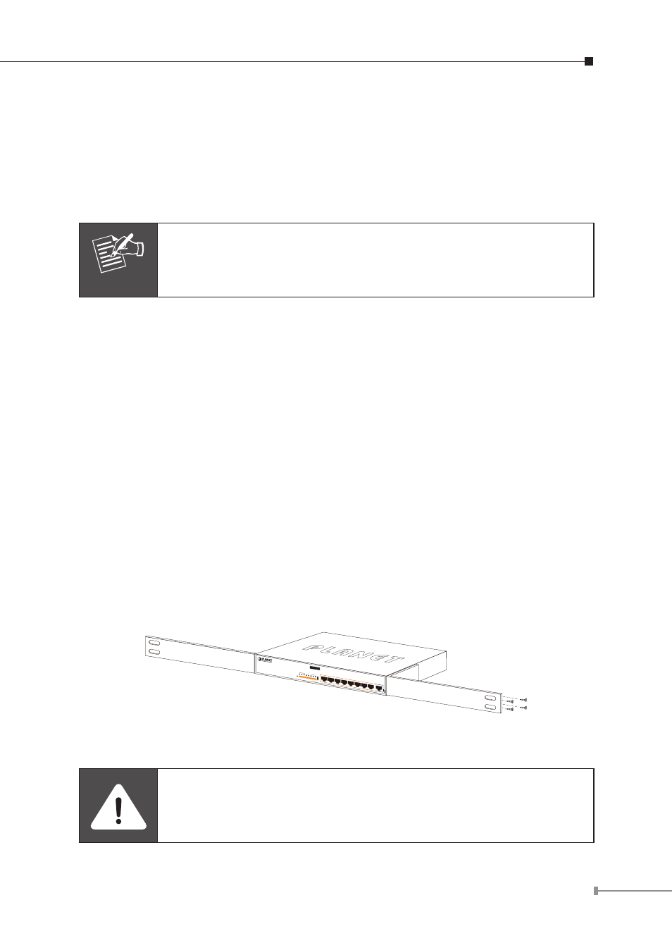
Step 2: Attach a rack-mount bracket to each side of the PoE Ethernet Switch with
supplied screws attached to the package. Figure 2-6 shows how to attach
brackets to one side of the PoE Ethernet Switch.
PoE
8-Port 10/100Mbps+1 G
igabit
802.3af
PoE Switch
FGSD-910P
1
PWR
2
3
4
5
6
7
Speed
10/100
LNK/
ACT
Gigabit
8
9
ACT
LNK
8
9
7
6
5
4
3
2
1
Figure 2-6: Attaching the Brackets to the PoE Ethernet Switch
You must use the screws supplied with the mounting brackets.
Damage caused to the parts by using incorrect screws would invali-
date the warranty.