Single-phase current measurement – Amprobe PQ55A Power-Analyzer User Manual
Page 21
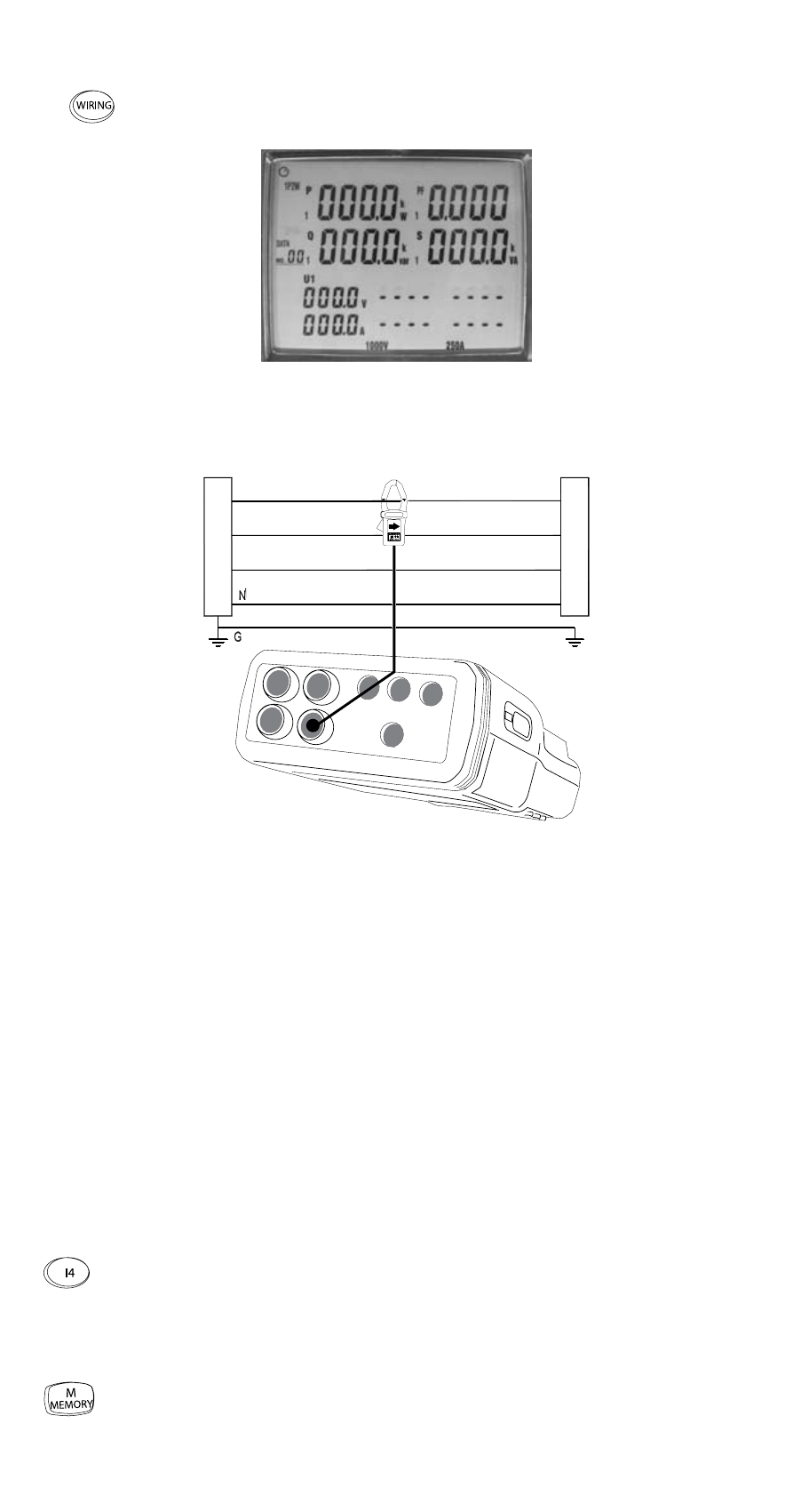
Single-phase Current Measurement
1) Switch on the instrument.
2)
Select the type of connection 1P2W using the “Wiring” function key
(6). After selection, the following display is indicated with the symbol
1P2W (5.11):
Display Type of connection 1P2W
The measurement inputs are connected as illustrated in the following drawing:
L1
L2
L3
Curr
ent Supply
Consumer
I4
Type of connection current measurement
L1: phase 1
L2: phase 2
L3: phase 3
N: neutral conductor
G: protective earth
☞
The printed arrow on the clamp adapter must point to the electric power supply.
1) Connect the test leads to the measurement instrument as follows:
2) Connect clamp adapter 4 to socket I4.
3) Now, connect clamp adapter to the conductor to be tested.
4) Open the clamp adapter 4 using the clamp opening lever and surround the live
phase.
☞
Make sure that the clamp completely surrounds the conductor and that there
is no air gap.
To display the current in the additional display (5.13), press the “I4” key
(13).
☞
The measurement range for the current measurement is between 0 and 250 A.
When exceeding the measurement range, “OL” appears on the display.
Individual measurements can be saved using the “M/MEMORY” key (19).
21