Emerson MICRO MOTION 1700 User Manual
Page 49
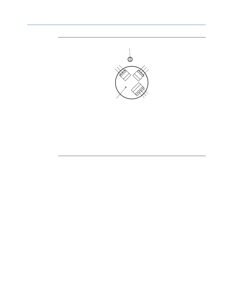
Model 2700 transmitter terminals
Figure 4-15:
A
B
C
D
E
F
G
H
I
J
K
A.
Brown
B.
Violet
C.
Yellow
D.
Orange
E.
Gray
F.
Blue
G.
White
H.
Green
I.
Red
J.
Mounting screw
K.
Ground screw (black)
4.5
Rotate the user interface on the transmitter
(optional)
The user interface on the transmitter electronics module can be rotated 90º or 180° from
the original position.
Mounting and sensor wiring for 9-wire remote installations
Installation Manual
45
This manual is related to the following products: