Emerson MICRO MOTION 1700 User Manual
Page 77
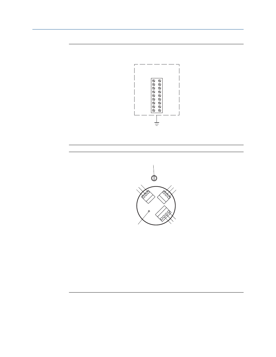
Model DT sensor terminals (user-supplied metal junction box with
terminal block)
Figure 5-24:
1
9
8
7
6
5
4
3
2
A
A.
Earth ground
Remote core processor terminals
Figure 5-25:
A
B
C
D
E
F
G
H
I
J
K
A.
Brown
B.
Violet
C.
Yellow
D.
Orange
E.
Gray
F.
Blue
G.
White
H.
Green
I.
Red
J.
Mounting screw
K.
Ground screw (black)
Mounting and sensor wiring for remote core processor with remote sensor installations
Installation Manual
73
This manual is related to the following products: