Ground the flowmeter components, 6 ground the flowmeter components – Emerson MICRO MOTION 1700 User Manual
Page 51
10.
Turn the display cover clockwise until it is snug.
11.
Replace the end-cap clamp by reinserting and tightening the cap screw.
12.
Restore power to the transmitter.
4.6
Ground the flowmeter components
In 9-wire remote installations, the transmitter/core processor assembly and sensor are
grounded separately.
CAUTION!
Improper grounding could cause inaccurate measurements or flow meter failure. Failure to
comply with requirements for intrinsic safety in a hazardous area could result in an explosion.
Note
For hazardous area installations in Europe, refer to standard EN 60079-14 or national standards.
If national standards are not in effect, adhere to the following guidelines for grounding:
•
Use copper wire, 14 AWG (2.5 mm
2
) or larger wire size.
•
Keep all ground leads as short as possible, less than 1
Ω impedance.
•
Connect ground leads directly to earth, or follow plant standards.
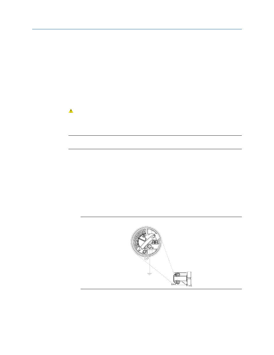
1.
Ground the sensor according to the instructions in the sensor documentation.
2.
Ground the transmitter/core processor assembly according to applicable local
standards, using the transmitter’s internal ground screw or the transmitter's
external ground screw.
Transmitter internal ground screw
Figure 4-17:
Mounting and sensor wiring for 9-wire remote installations
Installation Manual
47