Sensor and transmitter terminals, 1 sensor and transmitter terminals – Emerson MICRO MOTION 1700 User Manual
Page 47
Sensor and transmitter terminal designations
(continued)
Table 4-6:
Wire color
Sensor terminal
Transmitter terminal
Function
Gray
8
8
Right pickoff –
White
9
9
Left pickoff –
b. Tighten the screws to hold the wires in place.
c. Ensure integrity of gaskets, grease all O-rings, then replace the junction box and
transmitter housing covers and tighten all screws, as required.
4.4.1
Sensor and transmitter terminals
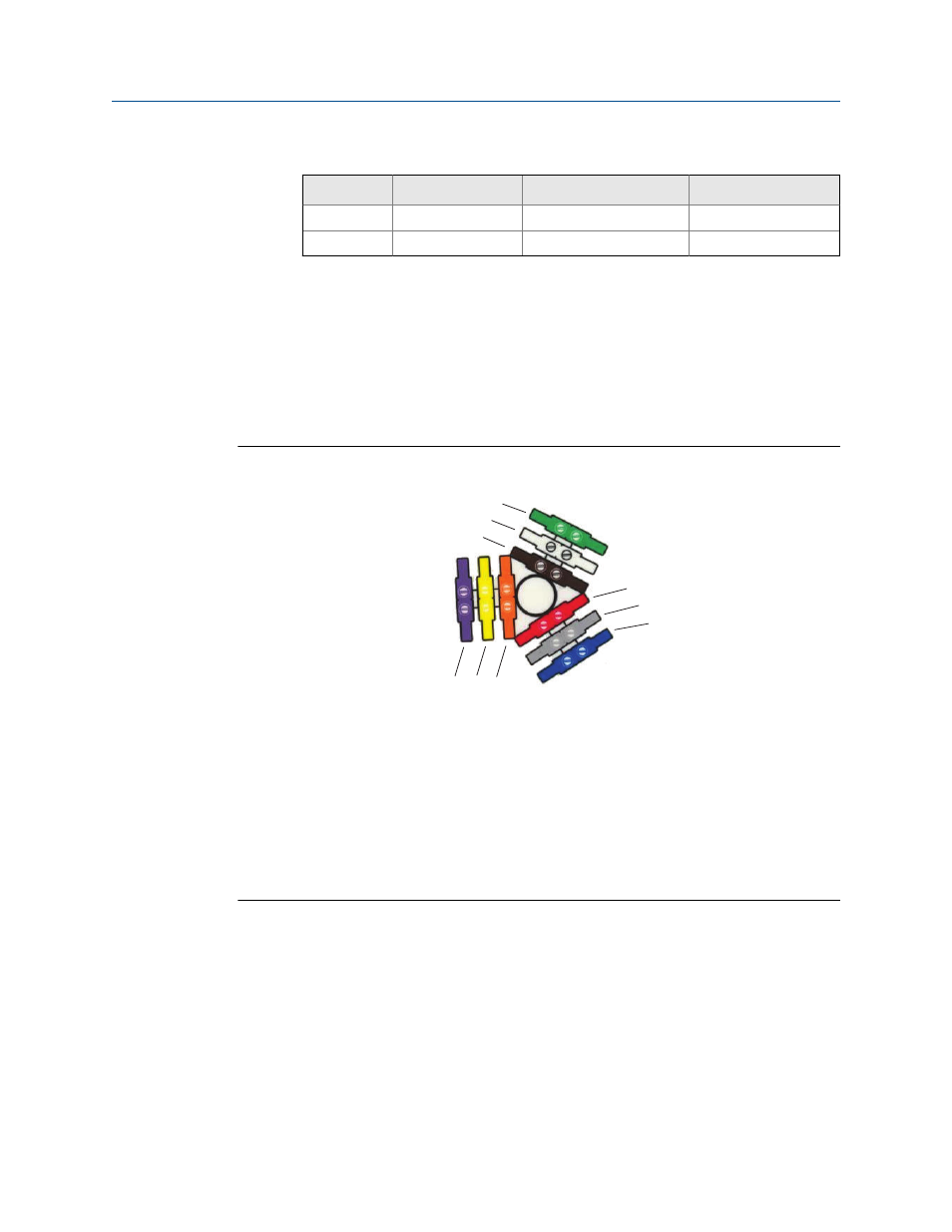
ELITE, H-Series, T-Series, and some F-Series sensor terminals
Figure 4-13:
D
I
H
F
E
A B C
G
A.
Violet
B.
Yellow
C.
Orange
D.
Brown
E.
White
F.
Green
G.
Red
H.
Gray
I.
Blue
Mounting and sensor wiring for 9-wire remote installations
Installation Manual
43
This manual is related to the following products: