Emerson MICRO MOTION 1700 User Manual
Page 28
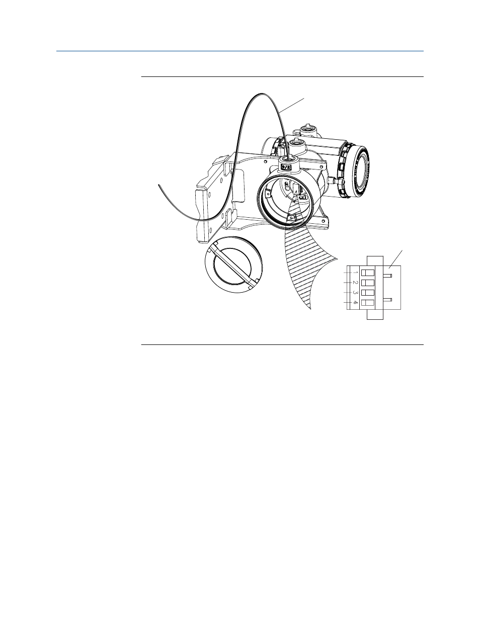
Wiring path for transmitters with stainless steel housing
Figure 3-8:
A
VDC+
VDC–
RS-485A
RS-485B
B
A. 4-wire cable
B. Mating connector
3.4
Rotate the user interface on the transmitter
(optional)
The user interface on the transmitter electronics module can be rotated 90º or 180° from
the original position.
Mounting and sensor wiring for 4-wire remote installations
24
Micro Motion
®
Model 1700 and 2700
This manual is related to the following products: