Ground the flowmeter components, 4 ground the flowmeter components – Emerson MICRO MOTION 1700 User Manual
Page 18
10.
Turn the display cover clockwise until it is snug.
11.
Replace the end-cap clamp by reinserting and tightening the cap screw.
12.
Restore power to the transmitter.
2.4
Ground the flowmeter components
In an integral installation, all components are grounded together.
If national standards are not in effect, adhere to the following guidelines for grounding:
•
Use copper wire, 14 AWG (2.5 mm
2
) or larger wire size.
•
Keep all ground leads as short as possible, less than 1
Ω impedance.
•
Connect ground leads directly to earth, or follow plant standards.
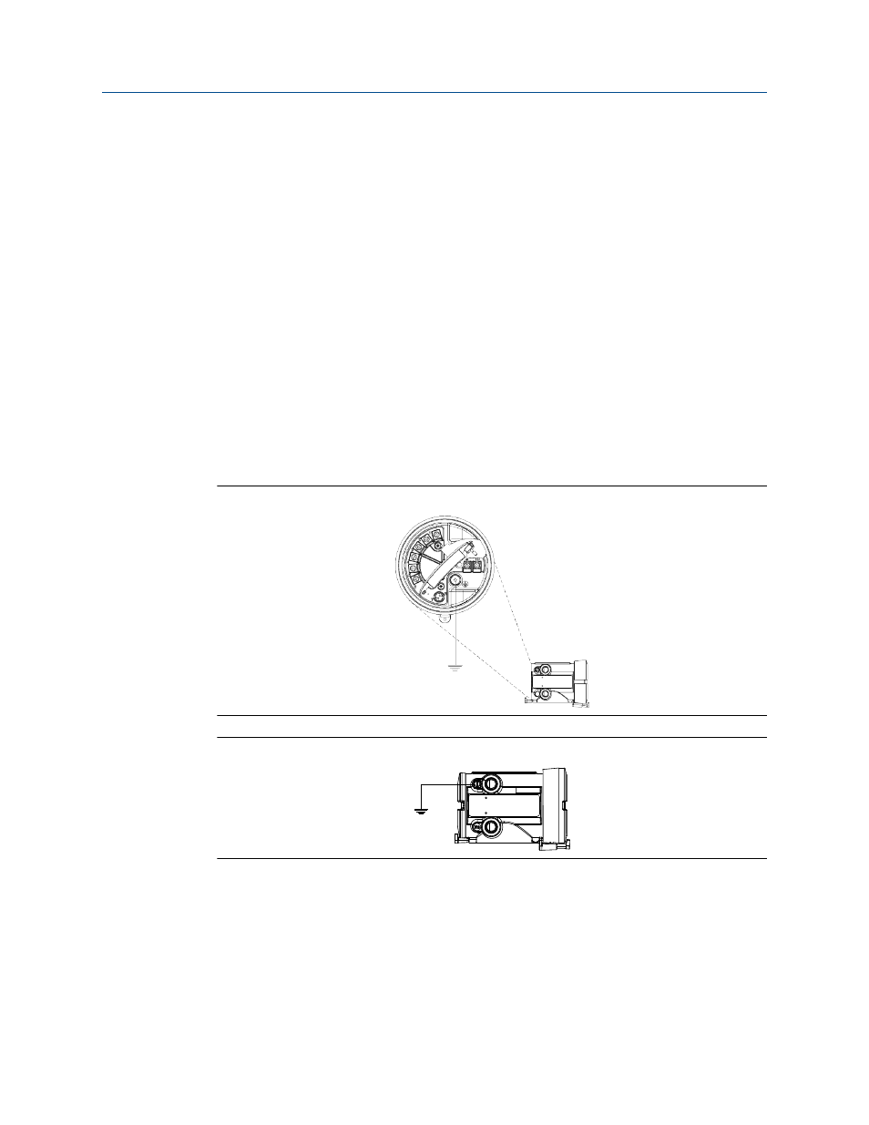
Ground via the piping, if possible (see sensor documentation). If grounding via the piping
is not possible, ground according to applicable local standards using the transmitter’s
internal or external ground screw.
Transmitter internal grounding screw
Figure 2-3:
Transmitter external grounding screw
Figure 2-4:
Mounting and sensor wiring for integral installations
14
Micro Motion
®
Model 1700 and 2700