Operation: cruise lights & aux (white/orange), Hi/low power (violet), Photocell hi/low – Whelen SZ8AAAA User Manual
Page 4: Scan-lock™ (white/violet), Page 4, 2 x 2 x 2 mode, All bar mode, Dip switch settings
Page 4
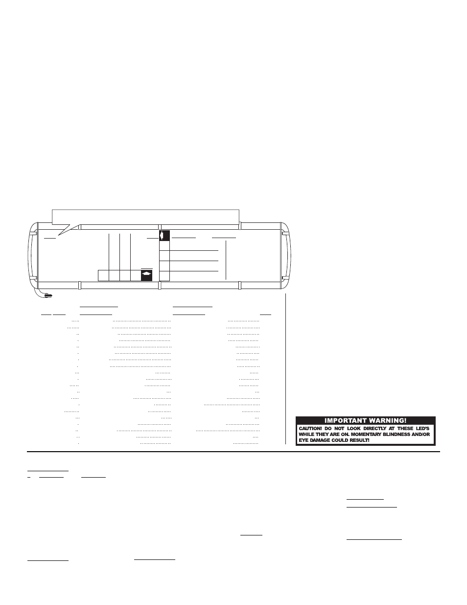
1. Input Control
2. Async or Sync
3. Warning-TA Pattern
4. Front TA
SW2
SW2
SW1
CONTROL CABLE: Applying +12 VDC to a control wire will activate the function until power is removed.
On:
Off:
2X2X2
All
B
ar
On: Off:
Front
TA
Of
f
Front
TA
On
1
ON
Switch On:
Switch Off:
Single
Dual
ON
GREEN
BLUE
BLU/WHT
GRN/WHT
BLU/BLK
GRN/BLK
WHT/BRN
WHT/RED
YELLOW
WHT/BLK
WHITE
WHT/BLU
VIOLET
WHT/ORG
RED
WHT/VIO
WHT/YEL
RED/WHT
RED/BLK
WHT/GRN
Front Corners
Rear Corners
Rear Outboards
Front Outboards
Rear Inboards
Front Inboards
Rear Center
Front Center
Passenger Alley in steady mode
Take-downs in steady mode
Driver Alley in steady mode
Take-downs and Alleys in flash mode
Low Power (See copy)
"A" corner LEDs in cruise mode
California Steady RED w/S/L
Flash Pattern Selection
Left Side TrafficAdvisor™
Only "B" outlets
Both "A" and "B" outlets
Right Side TrafficAdvisor™
(See copy)
1.
2.
3.
4.
5.
6.
7.
8.
9.
10.
11.
12.
13.
14.
15.
16.
17.
18.
19.
20.
Front Corners / Color 1
Rear Corners /
Rear Corners /
Front Corners /
Rear Directionals /
Front Directionals /
Rear Directionals /
Front Directionals /
Cruise - Aux
Not Used
Front Directionals in steady mode
Color 1
Color 2
Color 2
Color 1
Color 1
Color 2
Color 2
Passenger Alley in steady mode
Take-downs in steady mode
Driver Alley in steady mode
Take-downs & Alleys in flash mode
Low Power (See copy)
California Steady RED w/S/L
Flash Pattern Selection
TrafficAdvisor™
TrafficAdvisor™
(See copy)
Left Side
Right Side
1 AMP
1 AMP
1 AMP
1 AMP
1 AMP
1 AMP
1 AMP
1 AMP
1 AMP
1 AMP
1 AMP
1 AMP
1 AMP
1 AMP
1 AMP
.5 AMP
1 AMP
1 AMP
1 AMP
1 AMP
NOTE: SW1 switches
are factory set and
do not need to be
changed unless you
change lightheads.
On:
Off:
ASYNC
SYNC
On:
Off:
W
a
rning/T
A-Of
f
W
a
rning/T
A-On
1
On:
Off:
Single Front Corner
Dual Front Corner
4
On:
Off:
Single Rear Directional
Dual Rear Directional
2
On:
Off:
Single Rear Corner
Dual Rear Corner
3
On:
Off:
Single Front Directional
Dual Front Directional
2 X 2 X 2 Mode
Wire Function
Wire Function
Fuse @
WIRE
POS
ALL BAR Mode
SW1:
ON: Single Front Corner
OFF: Dual Front Corner
ON: Single Rear Corner
OFF: Dual Rear Corner
ON: Single Front Directional
OFF: Dual Front Directional
ON: Single Rear Directional
OFF: Dual Rear Directional
Switch 1
operation.
Switch 1
operation.
Switch 2
operation.
Switch 2
operation
Switch 3
operation.
Switch 3
operation.
Switch 4
operation.
Switch 4
operation.
There are 2 banks of Dip Switches inside the lightbar.
Controls Single or Dual operation for corners
& directionals.
controls function.
SW1
SW2
Dip Switch Settings:
2
3
4
SW2:
ON:
2X2X2
OFF:
All Bar
ON:
Asynchronous
OFF:
Synchronous
Switch 1
Enables
operation
Switch 1
Enables
operation.
Switch 2
Operates in
mode
Switch 2
Operates in
mode
Switch 3
Normal Operation
ON:
Switch 3
Activates
OFF:
WARNING/TA
OFF:
FRONT TA
Switch 4
Activates
ON:
Switch 4
Normal operation.
NOTE: The lightbar is shipped from the factory with all SW2 Dip Switches
in the "ON" position unless ordered differently by the customer.
TO CHOOSE A PATTERN: Allowing the desired pattern to run for more than 5
seconds will lock it in as the default pattern.
TO RESET TO THE FACTORY DEFAULT PATTERN: Turn off all lightbar functions.
Apply +12 volts to the Scan-lock™ wire and turn the appropriate function back on
and it will now be restored to its factory default pattern.
A momentary switch is preferred. Refer to the chart for available flash patterns.
All Bar activates all lightheads except Alleys and Take-downs, which can be
activated using the control wires. All Bar has 3 settings, each consisting of 12 to 16
flash patterns which run consecutively (See list). The phasing in All Bar will change
depending on how many outlets are activated. With All Bar, you won’t have to set
individual lightheads since the lightheads are activated and programmed in groups.
2 X 2 X 2 In this mode you can program Front or Rear; Corners, Inboards,
Outboards, Centers, Alleys or Traffic Advisor™ separately.
Warning/TA In WARNING/TA mode (with color 2 outlets active) the lightbar runs in
TA mode for 4 cycles, warning mode for 2 cycles and then repeats.
Async-Sync: While In 2X2X2 mode, Corners and Directionals can be programmed
to flash randomly (Asynchronous) or alternately (Synchronous) by setting dip switch
SW2-2. Using the Corners as an example, set to Synchronous, they left corner will
alternate with the right corner. In ASynchronous the corners will flash randomly.
California Steady RED: With the RED wire activated, use Scan-lock™ to choose
between the Front Driver Side Outboards, Front Driver Side Inboards, Front Driver
Side Centers, Front Driver/Passenger Outboards, Front Driver/Passenger Inboards
or Front Driver/Passenger Centers. Whichever you select (using Scanlock™) will run
in California Steady RED
Operation:
Cruise Lights & AUX (WHITE/ORANGE):
Cruise lights have 3 modes. MODE 1 (Default) - Cruise Lights are activated in Low
Power mode. MODE 2 - Cruise Lights are activated in a Lower power mode. MODE
3 - Off. Activate the WHITE/ORANGE wire and select a mode using Scan-Lock™.
Only the COLOR 1 corner LEDs are on in cruise mode.
Hi/Low Power (VIOLET):
The type of switch used depends on how you wish the Hi/Low feature to function:
Latching Mode: Apply +12 VDC to the VIOLET wire for less than 1 second and the
lightbar is “latched” into low power. Turn the unit off and then back on to restore
normal, high power operation. (momentary switch)
Level Mode: Applying +12 VDC to the VIOLET wire for over 1 second holds the
lightbar in low power mode until voltage is removed. (toggle switch)
Photocell Hi/Low:
Photocell Hi/Low will automatically change to a lower intensity as it gets darker out.
Scan-Lock™ (WHITE/VIOLET):
TO CYCLE FORWARD THROUGH AVAILABLE PATTERNS: Activate ONLY the
control wire of the function you wish to effect, then apply +12 volts to the WHT/VIO
wire for less than 1 second and release. Repeat until the desired pattern is displayed.
All Bar Setting 1
#
PATTERN
PHASING
1.
SignalAlert™ 75
ALT
2.
DoubleFlash 120
CHEC
3.
SingleFlash 90
IN/OUT
4.
SingleFlash 75
SIM
5.
SingleFlash 120
ALT
6.
TripleFlash™ 90
CHEC
7.
SignalAlert™ 120
IN/OUT
8.
SingleFlash 75
SIM
9.
DoubleFlash 75
ALT
10.
SingleFlash 120
CHEC
11.
TripleFlash™ 120
IN/OUT
12.
SingleFlash 75
SIM
All Bar Setting 2
1.
SingleFlash 75
ALT
2.
SingleFlash 120
CHEC
3.
SingleFlash 90
IN/OUT
4.
SingleFlash 75
SIM
5.
SingleFlash 120
ALT
6.
SingleFlash 90
CHEC
7.
SingleFlash 120
IN/OUT
8.
SingleFlash 75
SIM
9.
SingleFlash 75
ALT
10.
SingleFlash 120
CHEC
11.
SingleFlash 120
IN/OUT
12.
SingleFlash 75
SIM
13.
SingleFlash 75
ALT
14.
SingleFlash 120
CHEC
15.
SingleFlash 120
IN/OUT
16.
SingleFlash 75
SIM
All Bar Setting 3
1.
SingleFlash 90
ALT
2.
SignalAlert™ 90
IN/OUT
3.
SingleFlash 120
CHEC
4.
SingleFlash 75
SIM
5.
DoubleFlash 90
ALT
6.
SignalAlert™ 90
IN/OUT
7.
SingleFlash 120
CHEC
8.
SingleFlash 75
SIM
9.
TripleFlash™ 90
ALT
10.
SignalAlert™ 90
IN/OUT
11.
SignalAlert™ 120
CHEC
12.
SingleFlash 75
SIM
2 X 2 X 2
1.
SignalAlert™ 75
2.
CometFlash® 75
3.
DoubleFlash 150
4.
DoubleFlash 75
5.
SingleFlash 375
6.
SingleFlash 150
7.
SingleFlash 75
8.
ActionFlash™ 150
9.
ModuFlash™
10.
ActionScan™
Other Patterns
Take-downs and Alleys
1.
SingleFlash 240 ALT
2.
DoubleFlash 120 ALT
3.
SingleFlash 240 Sim
4.
DoubleFlash 120 Sim
Traffic Advisor Sequence
1.
Sequence to Solid
2.
Sequence on Sequence off
3
One Lamp Triple
4.
Two Lamp Triple
ALT = Alternating CHEC = Checkerboard Pattern IN/OUT = Flashes from inside to outside SIM = Simultaneous BOLD TYPE = California Title XIII compliant