Routing your lightbar cable(s), Control cable, Power cable – Whelen SZ8AAAA User Manual
Page 3: Page 3, 5" mounting foot
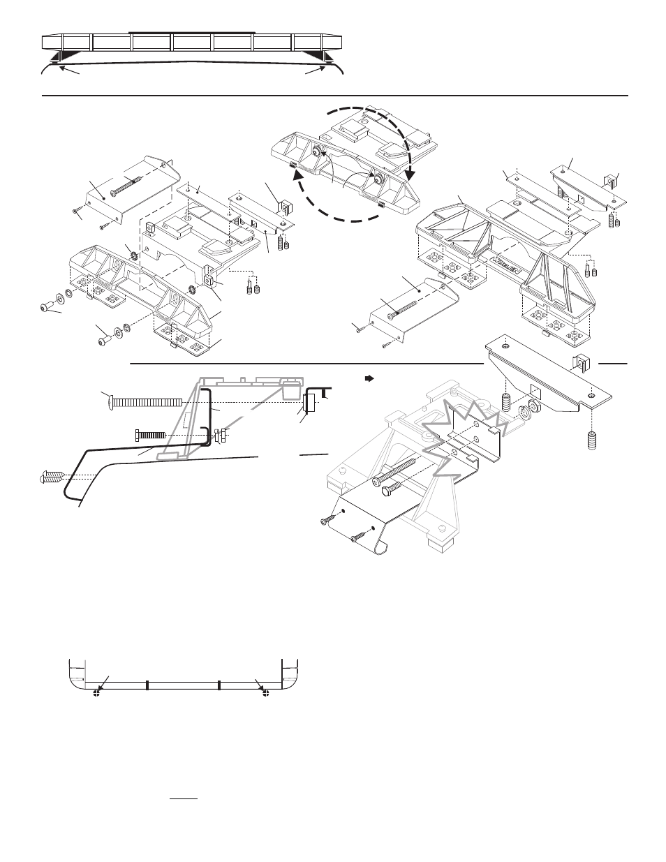
Page 3
Drill cable access hole in appropriate area
REAR OF LIGHTBAR
For cables exiting
the Driver-side
For cables exiting
the Passenger-side
NOTE: Unless otherwise specified, the lightbar mounting feet must be
sitting as close to the edge of the roof as possible, in full contact with
the roof and not be hanging off the edge.
IMPORTANT: For strap mounted bars, be sure you have the right size
lightbar for your vehicle. The bar should be approximately the same
width as the vehicle roof. If too large or small it will not mount properly
to the vehicle and may come loose.
Locking
Plate
Mounting
Foot
Nut
Mounting
Pad
Adjustment
screws
Lock
Washer
Anchor
Plate
Tinnerman
Nut
Tinnerman
Nut
Anchor
Plate
Locking
Plate
Mounting
Strap
Mounting
Screw
Adjustable Mounting Foot / Model MKAJ
Standard Mounting Foot / Model MKEZ
Tighten
screws
with
torque
wrench
set
at
35
to
40
in/lbs
Mounting
Strap
Mounting
Screw
Tension
Bolt
Tension
Bolt
Model
MKAJ
Mounting
Foot
5" Mounting Foot
BOLT
METAL SCREW
NOTE: The mounting straps are made to fit the contours of individual
vehicles. The strap shown here is for example only. The strap
for your vehicle may look different.
NOTE:
NOTE:
STRAP
S H E E T
M E T A L
SCREWS
MOUNTING FOOT
TINNERMAN
NUT
FOOT
ANCHOR
PLATE
SET
SCREW
Plate slides into
lightbar extrusion
NUT
SPLIT LOCK
WASHER
EXTENSION
VEHICLE ROOF
1/2" Minimum Clearance at Closest Point
Mounting should be feet as close to edge of roof as possible
On this model you may loosen the screws on the rear of the foot and adjust the
angle of the lightbar. This is used if the angle of the roof is not level with the road.
IMPORTANT: To adjust the leveling screws you must use a torque wrench
set at 35 to 40 ft. lbs
IMPORTANT! The lightbar should be a minimum of 16" from any
radio antennas!
Routing your Lightbar Cable(s)
1. To protect the headliner from damage, allow a 5” to 7” distance between roof
and headliner by lowering the headliner before drilling.
WARNING!There may be a roof support member that spans the distance
between the driver’s and passenger’s side. DO NOT DRILL THROUGH
THIS MEMBER! Adjust the location until the hole can be drilled without
contacting this support member.
2. Using a 1” hole saw, drill the cable access hole. Use a round file to smooth
and de-burr the edges than insert a 1” grommet.
3. Insert cable(s) through cable access hole into the vehicle. Use RTV silicone
to weatherproof access hole after the cable(s) are pulled completely into
vehicle. Route the cable(s) following manufacturers recommendations.
WARNING: Many vehicles are now equipped with side curtain and
B-pillar air bags. Alternate routing may be required.
WARNING! All Customer supplied wires that connect to the positive
terminal of the battery must be sized to supply at least 125% of the
maximum operating current and FUSED at the battery to carry that load.
DO NOT USE CIRCUIT BREAKERS WITH THIS PRODUCT!
Control Cable:
Refer to the chart on the next page for wire function and fusing. Apply +12 VDC
to a control wire to activate it’s function. Extend the control wires to a customer
supplied switch box and connect following the switch box instructions.
Power Cable:
1. Open the wire shield lid and route the power cable into the wire shield,
towards the firewall. Do not to pinch or crush any wires.
2. Follow the factory wiring harness through the firewall. If you need to drill a
hole in the firewall, be sure there are no components that could be
damaged. After you drill the hole, insert a grommet to protect the cable.
3. Route the cable along the factory wiring harness to the battery.
4. Install a 30 amp fuse block (customer supplied) on the end of the RED wire
in the power cable. Remove the fuse from the fuse block before connecting
any wires to the battery.
5. Connect the fuse block to the POSITIVE (+) terminal on the battery. Leave
no more than two feet of wire between the fuse block and the battery. The
wire between the fuse block and the battery is “unprotected”, do not allow
this wire to touch any other wires.
6. Connect the BLACK wire to the factory chassis ground.