Pin assignments and wiring, Hdmi connector pin assignments, Tp cable termination – Extron electronic Digital Video Transmitter and Receiver HDMI 201 Tx/Rx User Manual
Page 19: Pin assignments and wiring -22, See "tp cable termination, Installation and operation, cont’d
HDMI 201 Tx/Rx • Installation and Operation
Installation and Operation, cont’d
2-22
HDMI 201 Tx/Rx • Installation and Operation
2-23
l
Output Audio — Plug an audio device into this pair, left and
right, of female RCA connectors (figure 2-14) for an unbalanced
stereo audio signal.
Pin assignments and wiring
HDMI connector pin assignments
Figure 2-19 defines the pinout for the HDMI protocol.
Pin
Signal
1
TMDS data 2+
TMDS data 2-
TMDS data 0–
TMDS clock-
+5 V power
Hot plug detect
CEC control*
Reserved
(NC)
TMDS data 1+
TMDS clock+
TMDS clock
shield
SDA
DDC / CEC
Ground
TMDS data 2
shield
Pin
Pin
Signal
Signal
2
7
13
4
10
16
11
17
12
18
19
* CEC control on pin 13 is a proprietary
usage, not the industry standard.
14
3
TMDS data 0-
TMDS data 0
shield
8
9
SCL
15
TMDS data 1-
TMDS data 1
shield
5
6
HDMI
HDMI
Type A Receptacle
Type A Plug
1
18
2
19
1
18
2
19
Figure 2-19 — HDMI connectors
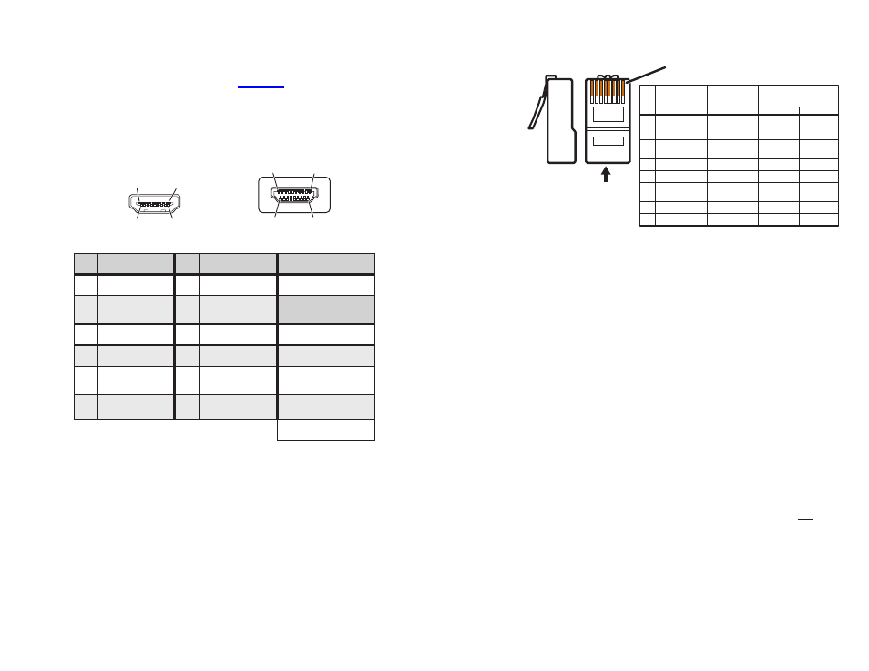
TP cable termination
N
RJ-45 termination with CAT 5, CAT 5e, or
CAT 6 cable must comply with the TIA/EIA T 568A or
TIA/EIA T 568B wiring standard for all connections.
Figure 2-20 details the recommended termination of TP cables
with RJ-45 connectors in accordance with either the
TIA/EIA T 568A
or the TIA/EIA T 586B wiring standard.
5
Pin
1
2
3
6
7
8
4
N
Terminate both ends of both cables identically, in accordance with
either the TIA/EIA T 568A or the TIA/EIA T 568B wiring standard.
Wire color
White-green
Green
White-orange
White-blue
Orange
White-brown
Brown
Blue
Data 0+
Data 0–
Data 1–
ID Clock–
Data 2+
Data 2–
Wire color
White-green
Green
White-orange
White-blue
Orange
White-brown
Brown
Signal
TIA/EIA T
586 A
TIA/EIA T
586 B
RJ-45 #1
ID Clock+
Data 1+
Blue
CEC
HPD
RS-232
TX
+12 V
RS-232
RX
DDC data
Ground
RJ-45 #2
DDC Clk
Side
12345678
Insert
Twisted
Pair Wires
Pins:
RJ-45
Connector
Figure 2-20 — TP cable termination
N
Do not use Extron’s UTP23SF-4 Enhanced Skew-Free
™
A/V UTP cable to link the transmitter and receiver.
Skew-free A/V cable was designed for most Extron
TP transmitter/receiver applications, but the
HDMI 201 Tx/Rx does not work properly with this
cable.
N
In order to fit in the junction box, the TP cables and
RJ-45 connectors should not have a boot installed.
N
If necessary, test for proper cable connection (output 1 to
input 1, output 2 to input 2) as follows:
1. Plug both TP cables into the powered unit.
2. Momentarily connect either of the cables on the
opposite end into the unpowered unit‘s “2” connector.
If the unpowered unit’s Power LED is lit, the
connection is correct.
If the unpowered unit’s Power LED is not lit,
unplug the connector on the unpowered end and
connect the other cable to the “2” connector.