0 alarm functions, 1 overvoltage and overtemperature protection, 2 undervoltage protection – KEPCO RCW 750W Series User Manual
Page 17: 3 fan failure, Alarm functions, Overvoltage and overtemperature protection, Undervoltage protection, Fan failure
RCW 350W 120607
13
4.0 ALARM FUNCTIONS
4.1 OVERVOLTAGE AND OVERTEMPERATURE PROTECTION
When the output voltage or the internal temperature of the RCW 750W Power Supply increases
beyond the specified values (see Table 1), the output is cut OFF and the fan turns OFF. To restart
(reset) the unit it is necessary to remove the ac input power, wait 40 seconds and then to reapply the
AC input power. However, when the Power Supply shuts down due to an increase in internal temper-
ature, the restart cycle (Power ON) should not begin until the temperature returns to within specifica-
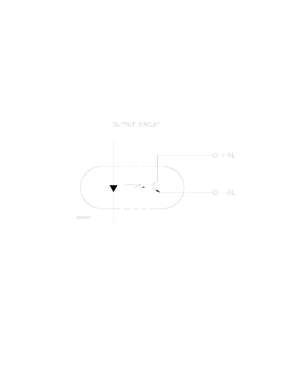
tions. Indication of an overvoltage or overtemperature condition is provided by a red LED and a logic
alarm output (at the ± AL terminals) that is attributable to an open collector-emitter circuit of an optical
coupler.
During normal operation, the optocoupler transistor is in full conduction (saturation) while during
alarm condition the transistor is open (stops conducting, see Figure 10).
FIGURE 10 LOGIC ALARM OPTICAL COUPLER OUTPUT FOR THE RCW 750W POWER SUPPLY
4.2 UNDERVOLTAGE PROTECTION
When the output voltage falls to less then 60% of the rated output voltage for more then 40 sec-
onds,(for the RCW 3.3-150K it is less than 45% for more than 40 seconds) the output is cut OFF
and the fan stops automatically .To restart (reset) the unit it is necessary to remove the ac input
power, wait 40 seconds and then to reapply the AC input power. An indication of undervoltage is
provided by a red LED and a logic alarm output (at the (±) AL terminals) that is derived from open
collector-emitter circuit of an optical coupler.
During normal operation, the optocoupler transistor is in full conduction (saturation) while during
alarm condition the transistor is open (stops conducting).
4.3 FAN FAILURE
A decrease in fan speed causes the output to shut down and the fans to turn OFF. To restart (reset)
the unit it is necessary to remove the ac input power, wait 40 seconds and then to reapply the AC
input power. Fan failure is indicated by a red LED and logic alarm output (at the ±AL terminals) from
an open collector-emitter circuit of an optical coupler.