Parallel connection of two rcw power supplies – KEPCO RCW 750W Series User Manual
Page 14
10
RCW 750W 120607
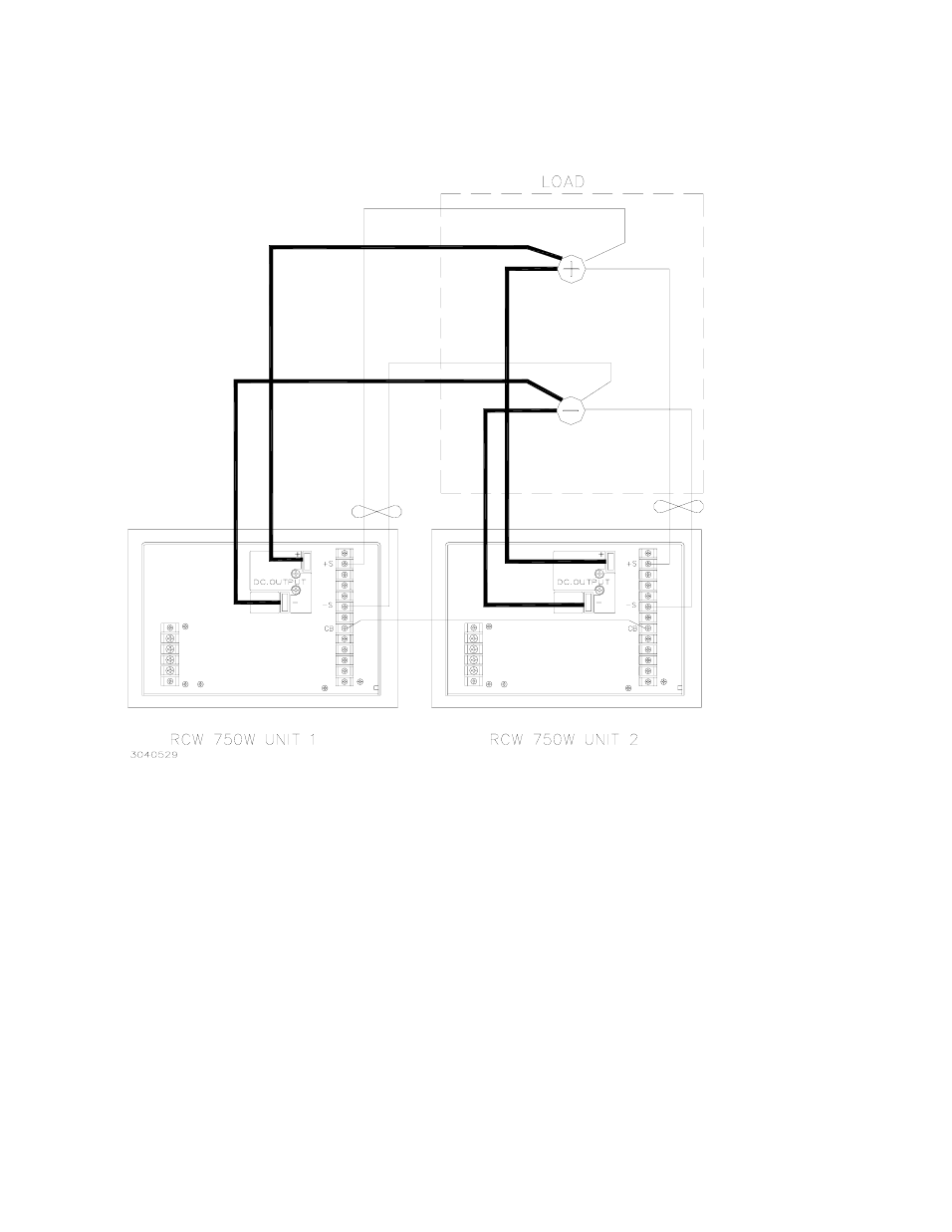
FIGURE 8 PARALLEL CONNECTION OF TWO RCW POWER SUPPLIES
NOTES
1) Maintain the connecting links between the (+) M and (+) S terminals and between the (–) M and (–) S terminal.
2) Set voltage of unit 1 to the desired voltage at the load.
3) With two RCW 750W units in parallel the output voltage of each Power Supply must be set to less than 2% of each other
4) When the Current Balance function is used with the Remote ON/OFF function, connect all the (+) RC terminals together and all
the (–) RC terminals together.
5) Use the same length and wire size for load connecting wires from the (+) and (–) Bus Bar of each RCW 750W Power Supply to
the load terminals
6) Use the same length and wire size for twisted pair Sensing wires from the (+) S and (–) S terminals of each RCW 750W power
Supply to the load terminals
1) Remove connecting links between the (+) M and (+) S terminals and between the (
-
) M and (
-
) S terminal.
2) Set voltage of unit 1 to the desired voltage at the load.
3) With two RCW 750W units in parallel the output voltage of each Power Supply must be set to less than 5% of each other
4) When the Current Balance function is used with the Remote ON/OFF function, connect all the (+) RC terminals together
and all the (
-
) RC terminals together.
5) Use the same length and wire size for load connecting wires from the (+) and (
-
) Bus Bar of each RCW 750W Power Sup-
ply to the load terminals
6) Use the same length and wire size for the twisted pair Sensing wires from the (+) S and (–) S Sense terminals of each
RCW 750W Power Supply to the load terminals