Chapter 4 serial ports – Remote Processing RPC-52 User Manual
Page 11
CHAPTER 4
SERIAL PORTS
Page 9
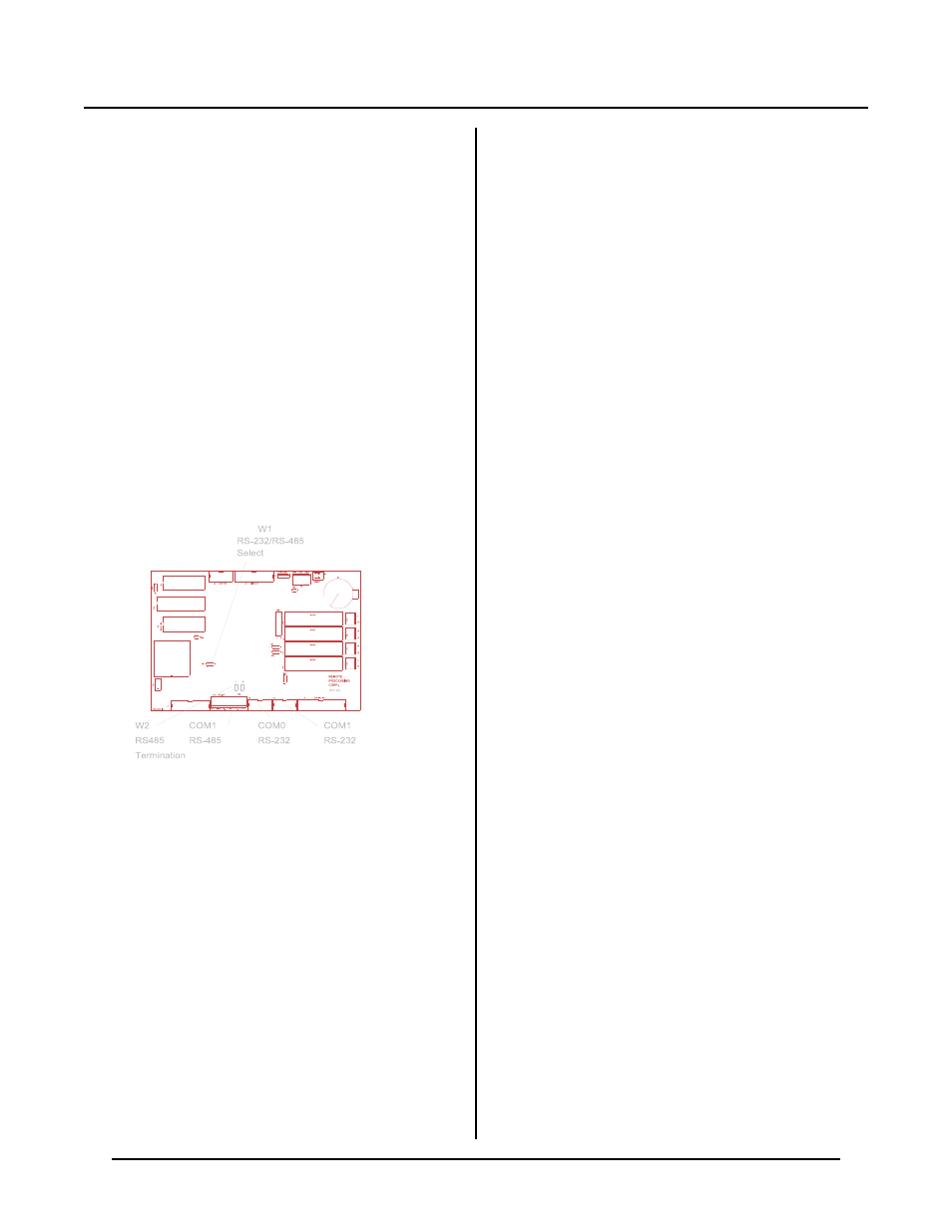
Figure 4-1 Serial port and jumper locations
DESCRIPTION
The RPC -52 has two serial ports that can be used for
interfacing to a printer, term inal, RS-485 network, or
other ser ial devices. This chapte r descr ibes their
characteristics and how to use them. F requent
references are made to commands listed in the BASIC-52
Programming Manual or RPBA SIC-52 Software
Supplement in this manual. Please refer to these
manuals for m ore inform ation about these comm ands.
Serial por ts are num bered C OM 0 and CO M1. COM 0 is
RS232 only and is used for progr am deve lopment.
During r un time, it can be used for other functions.
COM 1 is a general purpose port and can be used as
either RS-232 or RS-422/485.
Each port has a 256 character interr upt driven input and
output buffer. This allows characters to be sent out
(using PRINT) without slowing down program
execution. However, if the PRINT buffer fills, program
execution is suspended until all characters are in the
buffer. Both ports have a 256 character input buffer.
When m ore than 256 char acters are r eceived, excess
ones are ignored.
Your circuit board may have COM0 and CO M1 marked
as COM1 and CO M2. If this is the case, the silkscreen
is wrong and this manual should be followed.
COM0 SERIAL PORT
This port uses a VTC-9F serial cable to connect external
serial dev ices to the por t. T he cable con sists of a 10 pin
IDC connector wired one-to-one to a DB-9 connector.
Line 10 is sim ply cut off. The pin ou t is designed so it
plugs directly into the 9 pin serial port connector on a
P C .
COM 0 does not use hardware handshake lines. T he
CTS line is pulled high in case external equipment uses
this line.
This port is normally used for program ming. D uring
run tim e it may be u sed as a gene ral pur pose seria l port.
W h e n u s ed f or p r og r a m mi ng o r w i th th e IN P U T
s ta t em e n t, i t wi ll ac c ep t A S C II c ha r a ct e r v a lu e s f r om 0
to 127. When used with the GET function, it will return
ASCII values from 0 to 255.
COM1 SERIAL PORT
COM 1 is either an RS-232 or RS-422/ 485 port. A
VTC -9F serial cable, descr ibed above, is used for RS-
232 level communications. RS-485 is from screw
terminals. COM 1 is identical to COM0 except that
COM 1 has 2 hardware handshaking lines, C TS and
RTS. When RTS goes low, the RPC-52 is held off from
transmitting out COM1. The status of this port is read
by the LINE B statement. The example below retur ns
the status of the RTS line:
100 B = LINEB(2,5).AND.64
If B = 64, transm ission is held off.
The CT S line may be set high or low to hold off
comm unication. Line 400 se ts CTS high and 500 se ts it
low, or to hold off.
400 LINEB2,2,0A5H
500 LINEB2,2,0B5H
Jumper W 1 determines if COM 1 receive is RS-232 or
RS-422/485.
[1-2]
RS-485
[2-3]
RS-232 (de fault)
C O M 1 d ef a ul t i s R S -2 3 2. U s e th e C O NF I G BA U D
statemen t to set it to RS-422 or RS-485. When se t to
RS-422, the transm itter is always on. RS-485 mode
turns on the transmitter only when sending.
RS-422/485 Termination network
When the RPC-52 is the last physical unit on a network
(RS-485), or it is the only unit (RS-422), the receiver
must be terminated to prevent ringing. Jumper block
W2 installs or removes this network. Set W2 according
to the table below: