RISCO Group SMPS 3A User Manual
Page 12
12
SMPS - Installation Guide
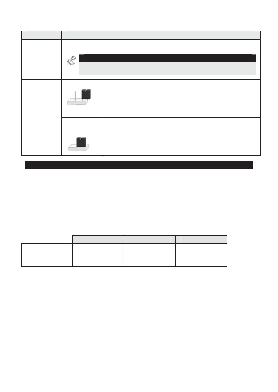
Jumper
Description
Bell/LS
Used to determine the SMPS mode of operation in accordance
with the sounder device connected to the BELL/LS terminals.
NOTE:
The sounder(s) connected to the SMPS operates identically to the
main panel’s sounder(s).
Bell
For a bell/electronic siren with a built-in siren
driver, position jumper on one pin; 12VDC is
produced at the sounder’s terminals during
burglary/panic alarms. Slow pulsing voltage is
produced during fire alarm.
LS
(Speaker)
For a loudspeaker without a built-in siren driver,
position jumper on both pins. The SMPS produces
continuous oscillating voltage for burglary/panic
alarms and an interrupted oscillating voltage for fire
alarm.
Programming the SMPS
The following section describes additional dedicated SMPS software
functions added to the ProSYS software.
It is recommended to read and fully understand the ProSYS installation
procedure before programming the SMPS!
Up to 8 PS modules may be connected (1.5A regular PS or 3A SMPS).
Up to 8 Utility Output Expansion Modules may be connected to the ProSYS
according to the following table:
ProSYS 16
ProSYS 40
ProSYS 128
Maximum UO
Expansion
Modules
2 4 8