RISCO Group SMPS 3A User Manual
Page 11
SMPS - Installation Guide
11
DIP Switches Settings
Module
Dip Switch
Description
PS/SW1-
SW3
Used to set a unique ID number for the Bus
module for communication purposes.
Power
Supply
PS/SW4
Enables/Disables Power Supply - ProSYS
communication
On (up): Communication enabled.
Off (down): Communication disabled
UO/ SW1-
SW3
Used to set a unique Bus ID number for the UO
module located on the SMPS board.
Utility
output
UO/SW4
Enables/disables UO module - ProSYS
communication.
On (up): communication enabled.
Off (down): communication disabled
NOTE:
When PS/SW4, or UO/SW4 is Off, the ID number defined by SW1-SW3 is not
recognized by the ProSYS and can be used for the connection of another accessory
of the same category. The UO/PS LED will flash since there is no communication with
the main panel.
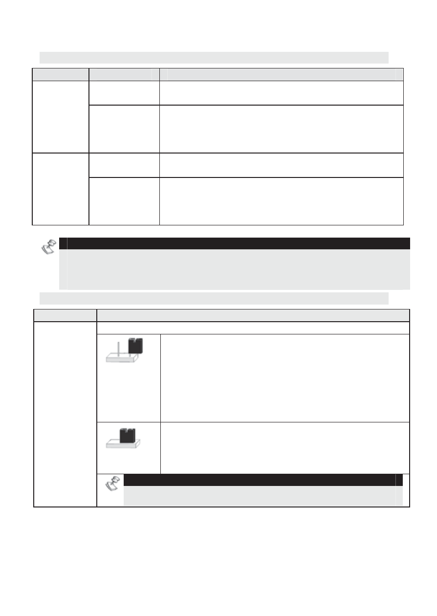
Jumper Settings
Jumper
Description
Battery discharge protection
Protection
ON
If a continuous AC power outage occurs, the
SMPS automatically disconnects the battery when
its backup battery voltage drops below 10.8VDC.
This is done to prevent "deep discharge” that may
damage the battery.
Protection
OFF
The battery may be totally discharged during
continuous AC failure (no deep discharge
protection).
BAT
NOTE:
If 2 pins configuration is selected, the battery might be damaged,
thus battery replacement may be required.