RISCO Group SMPS 3A User Manual
Page 10
10
SMPS - Installation Guide
Power Supply Components
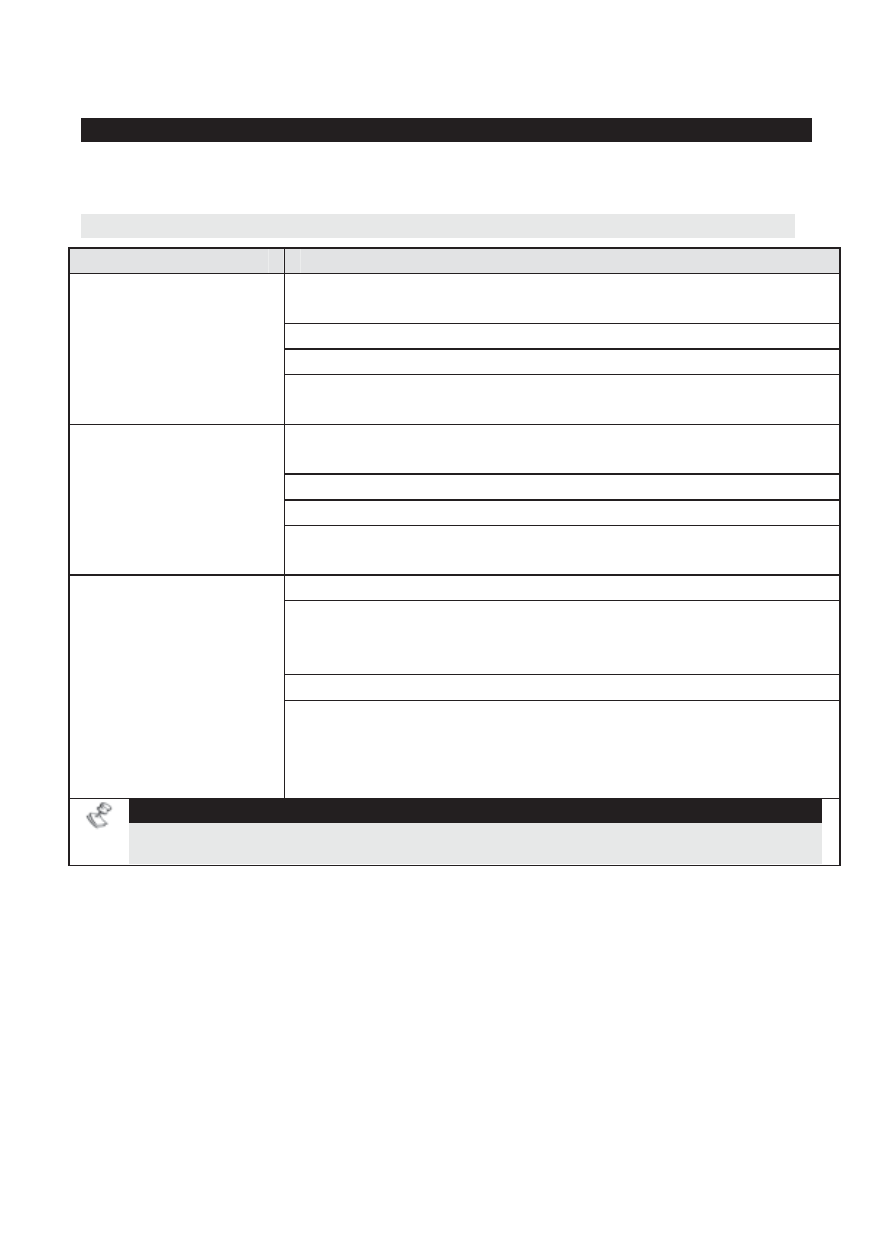
The LEDs, Dipswitches, jumpers, and terminals functions are described
herein.
LEDs Indication
LED
Description
Indicates communication status between the Power
Supply and the Main Panel.
On: Normal communication with the Main Panel.
Off: No input power
PS (Power Supply
Communication)
Flashing: Bus communication failure, system in
installation mode or PS dipswitch 4 is OFF.
Indicates communication status between the SMPS UO
module and the Main Panel.
On: Normal communication with the Main Panel.
Off: No voltage power
UO
(Utility Output
Communication)
Flashing: Bus communication failure, system in
installation mode or UO dipswitch 4 is OFF.
Indicates an actual/potential (calculated) overload.
On: Total current consumption from the AUX and
BELL/LS outputs exceeded 3A (power consumption
from both outputs will be disconnected).
Off: Normal current draw
OC
(Over Current)
Flashing: The SMSP detected a potential current
overload when calculating the total value of real current
consumption from the AUX output and expected current
consumption from the BELL/LS output.
NOTE:
To calculate sounder’s current consumption, the Sounder must be operated at
least once (recommended to be performed
upon installation completion).