Table 4-7. pci connector pin assignments (p15) – Emerson I/O MODULE IPMC7126E User Manual
Page 45
Chapter 4 Connector Pin Assignments
IPMC7126E/7616E I/O Module Installation and Use (6806800A45B)
31
57
RTS2_232
Not Used
58
59
CTS2_232
Not Used
60
61
MDO
MSYNC#
62
63
MDI
MCLK
64
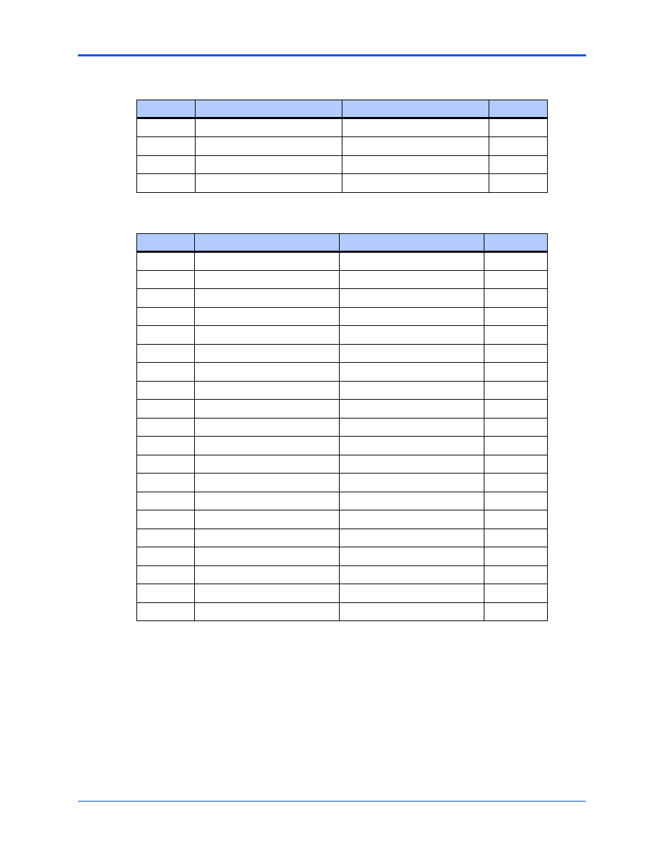
Table 4-7. PCI Connector Pin Assignments (P15)
Pin
Signal Description
Signal Description
Pin
1
I2CSCL
I2CSDA
2
3
GND
GND
4
5
DB8#
GND
6
7
GND
DB9#
8
9
DB10#
+3.3V
10
11
+3.3V
DB11#
12
13
DB12#
GND
14
15
GND
DB13#
16
17
DB14#
+3.3V
18
19
+3.3V
DB15#
20
21
DBP1#
GND
22
23
GND
LANINT2_L
24
25
PIB_INT
+3.3V
26
27
+3.3V
PIB_PMCREQ#
28
29
PIB_PMCGNT#
GND
30
31
GND
+3.3V
32
33
+5.0V
+5.0V
34
35
GND
GND
36
37
+5.0V
+5.0V
38
39
GND
GND
40
Table 4-6. PCI Connector Pin Assignments (P14) (continued)
Pin
Signal Description
Signal Description
Pin
This manual is related to the following products: