Table 4-6. pci connector pin assignments (p14) – Emerson I/O MODULE IPMC7126E User Manual
Page 44
IPMC7126E/7616E I/O Module Installation and Use (6806800A45B)
Chapter 4 Connector Pin Assignments
30
57
+5V (Vio)
Not Used
58
59
Reserved
Reserved
60
61
Reserved
GND
62
63
GND
Reserved
64
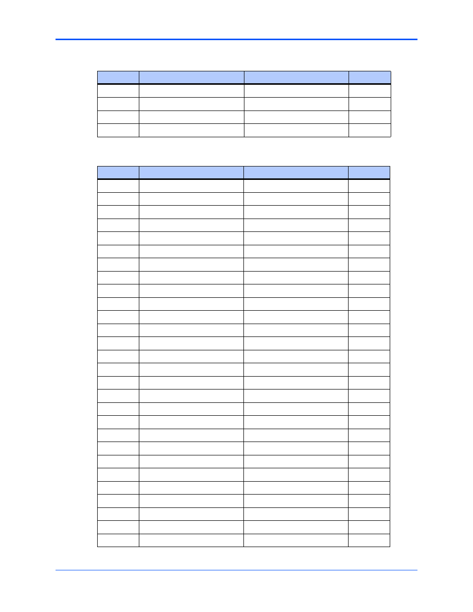
Table 4-6. PCI Connector Pin Assignments (P14)
Pin
Signal Description
Signal Description
Pin
1
Not Used
DB0#
2
3
Not Used
DB1#
4
5
Not Used
DB2#
6
7
Not Used
DB3#
8
9
Not Used
DB4#
10
11
Not Used
DB5#
12
13
Not Used
DB6#
14
15
PRSTB#
DB7#
16
17
PRD0
DBP#
18
19
PRD1
ATN#
20
21
PRD2
BSY#
22
23
PRD3
ACK#
24
25
PRD4
RST#
26
27
PRD5
MSG#
28
29
PRD6
SEL#
30
31
PRD7
D/C#
32
33
PRACK#
REQ#
34
35
PRBSY
O/I#
36
37
PRPE
AFD#
38
39
PRSEL
SLIN#
40
41
INIT#
TXD3
42
43
PRFLT#
RXD3
44
45
TXD1_232
RTXC3
46
47
RXD1_232
TRXC3
48
49
RTS1_232
TXD4
50
51
CTS1_232
RXD4
52
53
TXD2_232
RTXC4
54
55
RXD2_232
TRXC4
56
Table 4-5. PCI Connector Pin Assignments (P13) (continued)
Pin
Signal Description
Signal Description
Pin