Table 4-4. pci connector pin assignments (p12) – Emerson I/O MODULE IPMC7126E User Manual
Page 42
IPMC7126E/7616E I/O Module Installation and Use (6806800A45B)
Chapter 4 Connector Pin Assignments
28
57
+5V (Vio)
AD03
58
59
AD02
AD01
60
61
AD00
+5V
62
63
GND
REQ64#
64
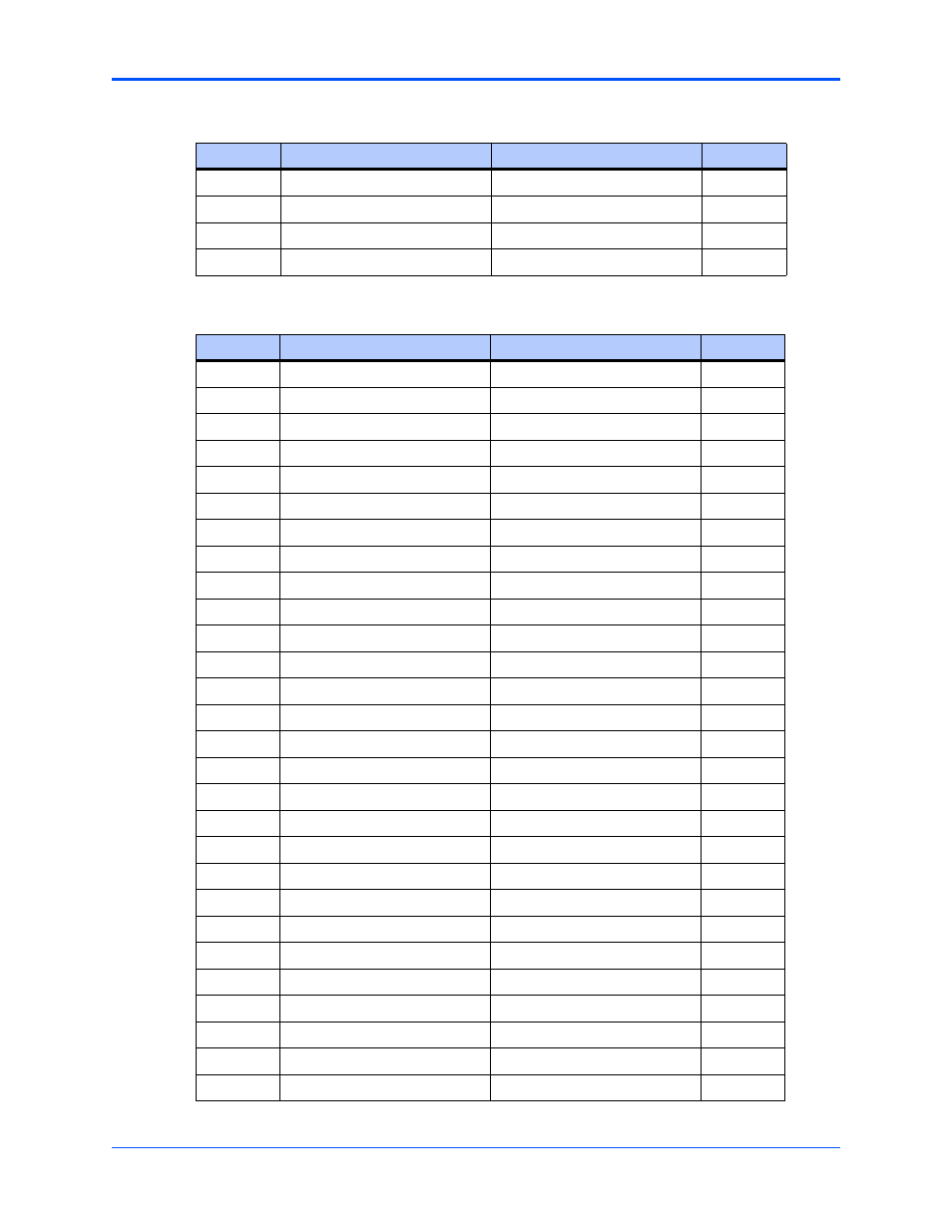
Table 4-4. PCI Connector Pin Assignments (P12)
Pin
Signal Description
Signal Description
Pin
1
+12V
TRST#
2
3
TMS
TDO
4
5
TDI
GND
6
7
GND
Not Used
8
9
Not Used
Not Used
10
11
Not Used
+3.3V
12
13
RST#
Not Used
14
15
+3.3V
Not Used
16
17
Not Used
GND
18
19
AD30
AD29
20
21
GND
AD26
22
23
AD24
+3.3V
24
25
IDSEL1
AD23
26
27
+3.3V
AD20
28
29
AD18
GND
30
31
AD16
C/BE2#
32
33
GND
Not Used
34
35
TDRY#
+3.3V
36
37
GND
STOP#
38
39
PERR#
GND
40
41
+3.3V
SERR#
42
43
C/BE1#
GND
44
45
AD14
AD13
46
47
GND
AD10
48
49
AD08
+3.3V
50
51
AD07
Not Used
52
53
+3.3V
Not Used
54
55
Not Used
GND
56
Table 4-3. PCI Connector Pin Assignments (P11) (continued)
Pin
Signal Description
Signal Description
Pin
This manual is related to the following products: