Controls and installation, cont’d, Ou tp ut sog out ddsp serr sp are – Extron Electronics RGB 103xi User Manual
Page 12
RM
RGB 103/109/112
xi
xi
xi
xi
xi Controls and Installation
LM
RGB 103/109/112
xi
xi
xi
xi
xi Controls and Installation
Controls and Installation, cont’d
2-12
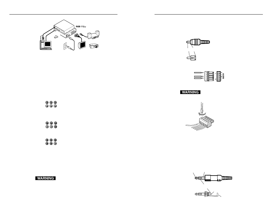
Figure 15 — RGB 112
xi
xi
xi
xi
xi installation
2. Connect the interface cable marked “Video input” to the
computer’s video output (where the monitor was
originally connected).
3. Connect the audio cable connector on the interface cable
to the computer’s audio line output (where the
powered speakers were originally connected).
4. Use BNC cables to attach the interface to a projector or
other display device.
RGsB
– If coax cables are connected and terminated
(75 ohms) to the red, green, and blue
channels only, and the SOG switch is
set to On (see page 2-4), the output will
be sync on green.
RGBS
– If the S (composite sync) cable is connected,
the output will be composite sync.
RGBHV
– If both the H & V cables are connected, the
sync output is separate horizontal and
vertical.
Connecting audio
Before connecting audio, determine whether your audio
system is unbalanced or balanced. Then, follow the
instructions on page 2-13 to connect unbalanced audio or
balanced audio.
Wiring the audio incorrectly may damage the
audio output circuits.
Unbalanced audio
To attach the interface to an unbalanced audio system, do
the following:
1. Attach the audio cable to an unbalanced speaker input
connector (tip and sleeve).
2. Attach the audio cable to the captive screw connector
(Extron part number
10-319-10). Fasten the
captive screws inside
the audio cable
connector as shown in
figure 16.
Connect the sleeve(s) to ground (GND).
Connecting the sleeve(s) to a negative (-)
terminal will damage audio output circuits.
Figure 16 — Fastening captive screws
3. Slide the audio cable connector into the audio output
connector on the interface.
Balanced audio
To attach the interface to a balanced audio system, do the
following:
1. Attach the audio cable to a balanced speaker input
connector (tip,
ring, and sleeve).
Unbalanced Output
Tip
See Warning
Sleeve (s)
Tip
See Warning
Tip (+)
Sleeve
Tip (+)
Ring (-)
Sleeve
RGBS
R
H
G
V
B
S
RGsB
R
H
G
V
B
S
RGBHV
R
H
G
V
B
S
Tip
Sleeve
2-13
Sun or SGI
Computer
Monitor
Projector
Audio
Power
or
OU
TP
UT
SOG OUT
DDSP
SERR
SP
ARE
Rear
50
/60
Hz
10
0-2
40
V
0.5
A
LE
VE
L/
PE
AK
0.8
V 5
0%
UN
ITY
0.9
V 1
00
%
BU
FFE
RED
LO
CA
L
MO
NIT
OR
OU
TPU
T
INP
UT
H. S
HIF
T
RG
B 10
9 xi
VG
A IN
TER
FAC
E W
/AD
SP
Front
or
MFTA