Controls and installation, cont’d – Extron Electronics RGB 103xi User Manual
Page 10
RM
RGB 103/109/112
xi
xi
xi
xi
xi Controls and Installation
LM
RGB 103/109/112
xi
xi
xi
xi
xi Controls and Installation
Controls and Installation, cont’d
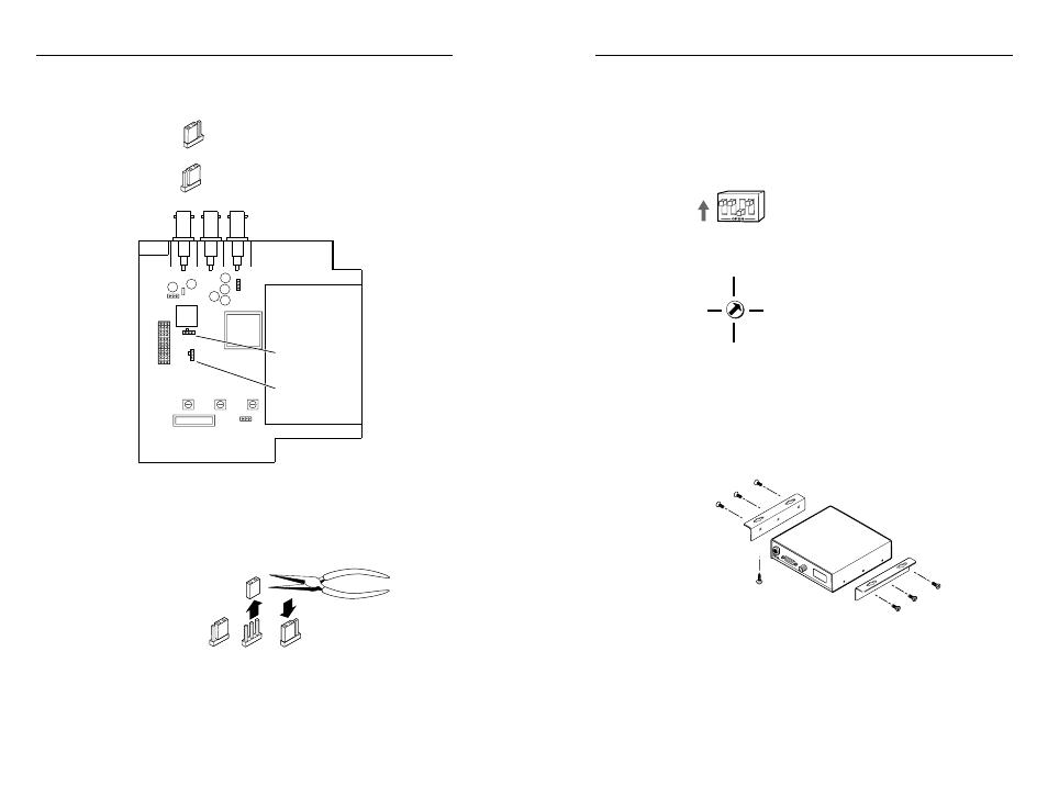
Setting configuration switches
DIP switches
The DIP (dual inline package) switches on the rear panel of
the interface control the sync on green output, Digital
Display Sync Processing, and serration pulses. The DIP
switches on the front of the RGB 109
xi provide ID bit
termination. Set DIP switches to either On (Closed) or Off
(Open) to select the desired function as
described in the sections on front and rear
panel features on pages 2-2 through 2-5.
CPU dial switch (RGB 112
xi
xi
xi
xi
xi only)
The CPU dial switch specifies the type of computer to
which the interface is attached. To
change the switch setting, insert a small
screwdriver in the slot in the center of the
dial, and turn the dial to the desired
position.
Mounting the interface
To mount the interface under a desk or in a podium using
the under desk mounting kit (Extron part number
70-077-01), do the following:
1. Attach the mounting brackets to the interface using six
machine screws supplied with the mounting kit (see
figure 9).
Figure 9 — Attaching the under desk
brackets (part number 70-077-01)
2. Using the to-scale template on page B-3 to guide you,
mark the four screw holes on the underside of the
surface to which you are mounting the interface.
3. Drill four pilot holes, each 3/32” in diameter by 1/4”
deep, where marked on the template.
2-9
3. Note the positions of jumpers J20 and J40 before
changing jumper settings (figure 7). There are two
possible setting combinations for 3-pin jumpers:
pins 1 and 2 connected
pins 2 and 3 connected
Figure 7 — Circuit board jumper locations
4. To change the jumper configuration, use pliers to pull
the jumper shunt off the pins, then place the jumper
on the appropriate pins (figure 8).
Figure 8 — Changing jumper settings
5. Replace and fasten the enclosure cover, reversing step 2.
2-8
BU
FFE
RED
LO
CA
L
MO
NIT
OR
OU
TPU
T
INP
UT
H. S
HIF
T
RG
B 1
03 x
i
MA
C IN
TER
FAC
E W
/A
DSP
1 and 2
2 and 3
3
4
1
2
IBM
SGI
SUN
SOG
J19
1
J40
1
J20
1
Front
Rear
Power Supply
J20: Sync polarity
jumper
J40: Vertical sync
width jumper