Hardware description – Epson C82305 User Manual
Page 22
HARDWARE DESCRIPTION
1. I/F board connector: EIA standard 25-pin D-SUB
female connector.
2. For signal description and pin assignment, refer to
the table below:
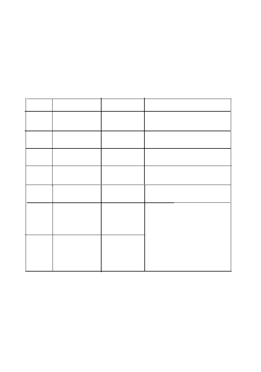
Table 9. Signal Description and Pin Assignment
Pin No.
Signal name
Direction
Description
1
protective
Ground
—
Chasis ground
Transmitted
2
Data (TXD)
Text
Transmitted serial data
3
Received Data
(RXD)
Ill
Received serial data
4
Request to
o u t
This signal is always at the
Send (RTS)
positive EIA level.
I
I
7
Signal Ground
In
Return path for data and
control signals.
Reverse
1 1
Channel
Out
(=2nd RTS)
Data Terminalk t
20
O u t
Ready (DIR)
This
signal is at he positive
EIA Level when the printer is
ready to accept data entry
and at the negative EIA
level when the printer is not
ready to accept data entry
Operator can invert the
polarity of the signal with
jumper 15.
19