Figure 2: typical xlc flying system – Electro-Voice XLC User Manual
Page 7
ELECTRO-VOICE
®
XLC
TM
Rigging Manual
6
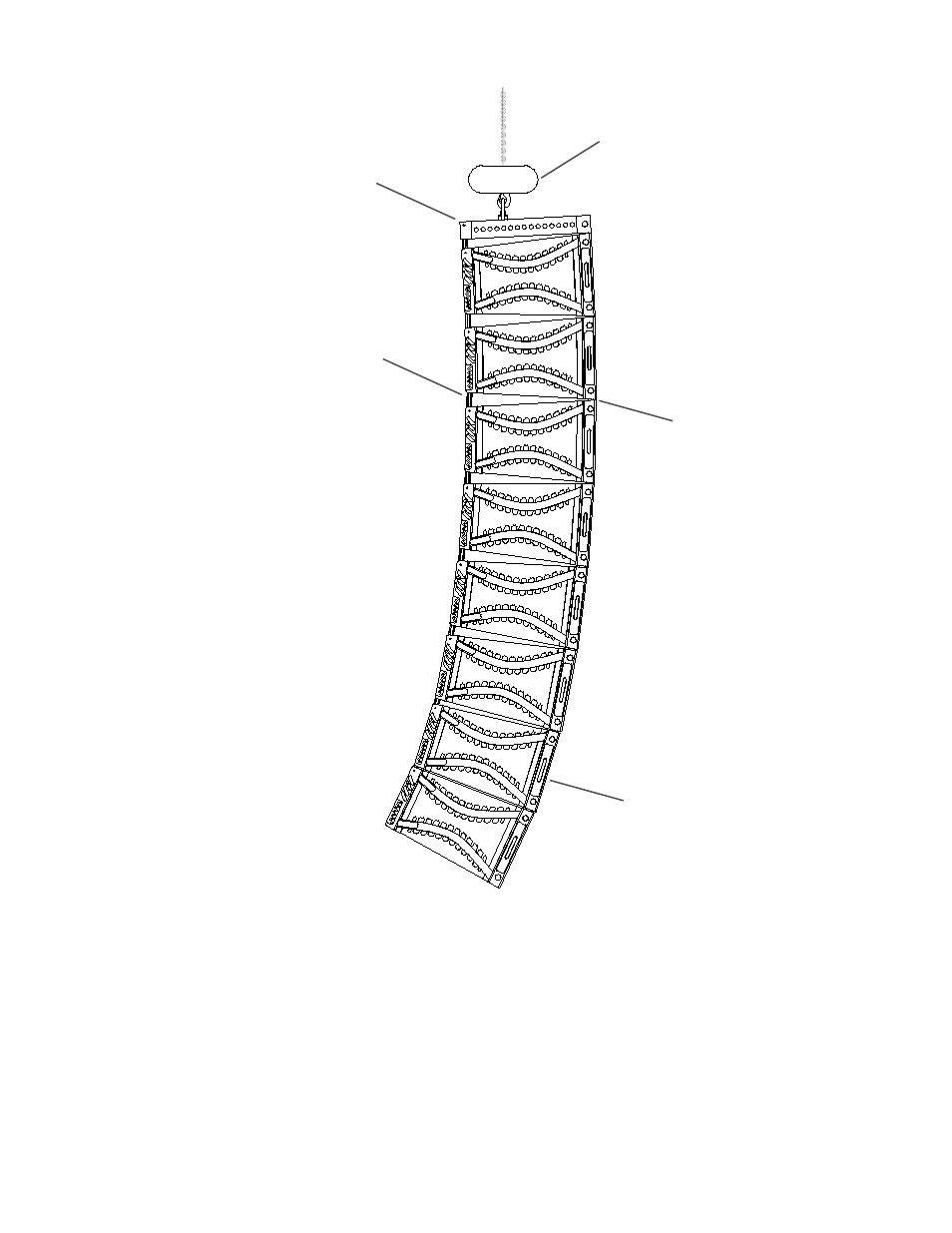
Figure 2:
Typical XLC Flying System
Hoist Motor
XLC Enclosures
Grid
Eight XLC Enclosures
Hinged at the Front by
the Button Bars and
Front Rigging Tubes
Angles Between
Enclosures fixed by Pins
through the Swing Arms
and Rear Rigging Slot
Holes
The swing arm from an enclosure below can be pivoted up so that one of the quick-release pins
may be inserted through the holes in the rigging slot on the frame and the slot in the swing arm,
linking the two enclosures together. The vertical tilt angle of the bottom enclosure is then
determined by the hole in which the swing arm is pinned. The XLC-127 and XLC-127+ enclosures
may be angled from 0° to 8° in 1° increments, while the XLC-118 enclosure may be angled from
0° to 12° in 1° increments. The angle adjustment holes are detailed in figures 4a and 4b. This pin
fixes the maximum distance the back corners of the enclosures may be separated.
Swing Arm
Button Bar
- 3-Inch High Frequency Neodymium Transducer ND6-8 (2 pages)
- Sx500+ (8 pages)
- 12-InchTwo-Way Full-Range Force i Monitor (2 pages)
- Constant-Directivity Horn HP420 (2 pages)
- Speaker System (56 pages)
- TX1152FM (2 pages)
- Loudspeaker System XiA-Series (1 page)
- Fri+122/64 (4 pages)
- EVID C12.2 (2 pages)
- ZX5-60 (4 pages)
- Phoenix (20 pages)
- EVA-2082S/920 (4 pages)
- 600W Loudspeaker System ZX3-60 (2 pages)
- Zx1i-100T (12 pages)
- Force i (2 pages)
- Two-Way High-Output Stage System Eliminator ii (2 pages)
- Sound Reinforcement System Xi-1123A/106F (4 pages)
- HPT64 (2 pages)
- FRX+660 (4 pages)
- FRi-2082 (2 pages)
- EVID FM6.2 (2 pages)
- EVID FM4.2 (2 pages)
- TX1152 (2 pages)
- EVF-1122S/66 (4 pages)
- FRX+181 (2 pages)
- Sx600 (16 pages)
- 12" Powered Subwoofer System EVID 12.1P (2 pages)
- XI-1152A/64F (4 pages)
- ZX4 (2 pages)
- Sx300 (2 pages)
- DH2T-16 (2 pages)
- Compact Powered Sound Reinforcement Speaker SxA250 (2 pages)
- Compact Full-Range Speaker EVID 4.2 (2 pages)
- EVF-1152D/64-FG (4 pages)
- Theatre Stage System TS940D (4 pages)
- Constant-Directivity Horn HP1240 (2 pages)
- Xi-1122MHA (1 page)
- EVID 6.2 (2 pages)
- DC-One (8 pages)
- SX300PIX (8 pages)
- XI-1122MHA/64F (4 pages)
- Plasma Series (16 pages)
- Dual 15-InchTwo-Way Full-Range Speaker System Force i25 (2 pages)
- ZXA590 (4 pages)