Kichler 337011 User Manual
Light wall control installation instructions, Installation and operating instructions, Warning
337011
INSTALLATION AND OPERATING
INSTRUCTIONS
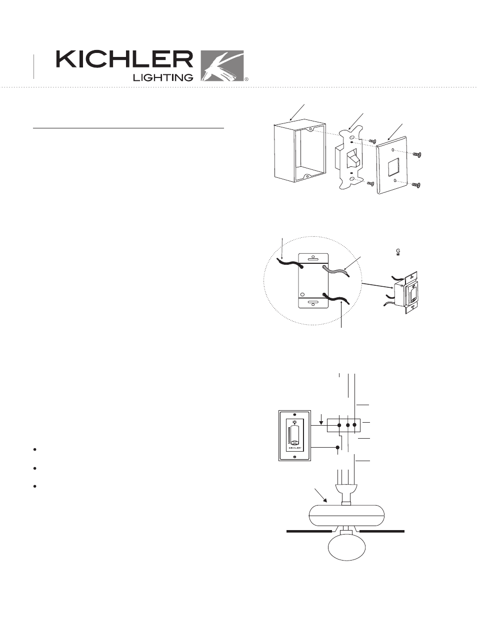
1. Disconnect the power and remove the existing wall plate and switch. (Fig. 1)
2. Push the slide switch all the way down to the OFF position. (Fig.2)
3. Make each of the wire connections illustrated in Figure 3. Secure each
with the wire nuts provided.
Connect the Black wire from the switch to the Black Household Supply
Wire (AC in L)
Connect the Green (ground) wire from the Switch to the Household
ground wire.
Connect the Black wire from the Switch to the Black wire leading to the
Blue wire on the Fan. This is the wire that controls the ceiling fan light
fixture. DO NOT connect this switch to the ceiling fan motor.
4. If your outlet box has a ground wire (green or bare copper) connect the
wall transmitter's ground wire to it; otherwise connect the wall transmitter's
ground wire directly to one of the screws from the outlet box.
WARNING
To avoid fire, shock and serious personal injury, follow these instructions:
1. Carefully read and retain this Instruction Manual for future reference.
2. To avoid possible electrical shock, be sure the electricity is turned off at
the main panel by removing the fuse or opening the circuit breaker.
3. This control switch is designed for use with "Ceiling Fans" ONLY. DO
NOT use with any other type of electrical appliance.
4. All wiring must conform to national and local electrical codes. If you feel
you do not have enough electrical knowledge, have a licensed electrician
install the control.
5. The total wattage for the lights 300W.
Fig. 2
Fig. 1
Fig. 3
1
LIGHT WALL CONTROL
INSTALLATION INSTRUCTIONS
Wall plate
Switch
Outlet box
Fan
SUPPLY CIRCUIT
BLACK
BLACK
B
L
A
C
K
B
L
U
E
B
la
c
k (
A
C i
n L
)
Ground Conductor
Outlet Box
Green Ground Lead
Ground to Downrod
G
R
E
E
N
W
H
IT
E
W
H
IT
E
Green ground ( )lead
Black (AC IN L)
to hot household
Black wire to Black
Household supply
wire in the ceiling
outlet box.