4 installing the device, Installing the device -5, Rd rack) – Enterasys Networks C1H124-24 User Manual
Page 33: Section 3.4
Installing the Device
Hardware Installation
3-5
4. Grasp the sides of the Mini-GBIC
and pull it straight out of the port slot
.
If storing or shipping the Mini-GBIC, insert the dust protector into the Mini-GBIC to protect the
fiber ports.
3.4
INSTALLING THE DEVICE
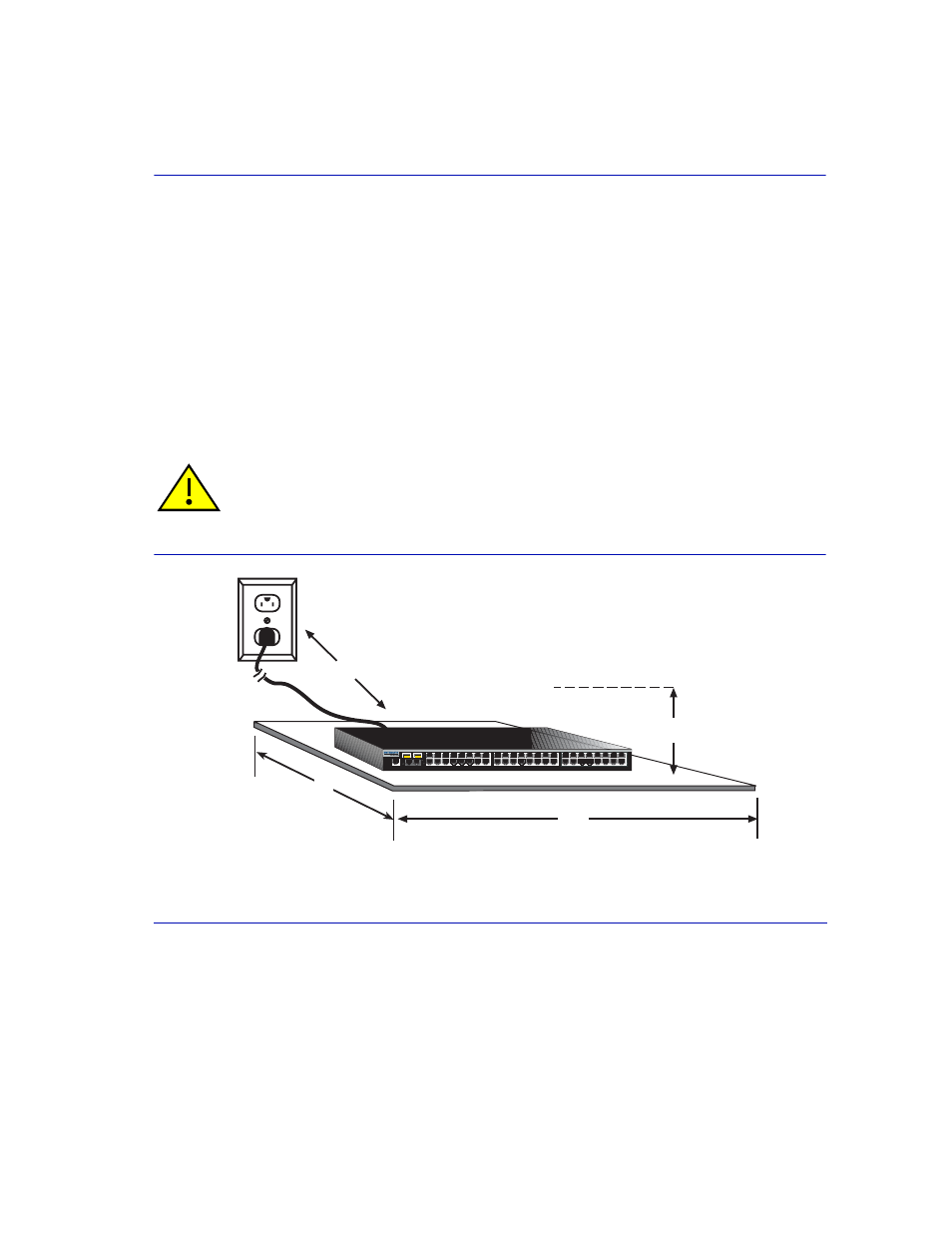
For a tabletop or shelf installation, locate the device within seven feet of its power source and on an
unrestricted free surface area as shown in
. If an optional redundant power system is
going to be installed and connected to the D-type cable connector on the rear of the device, refer to
the installation guide shipped with the redundant power system.
for power connection instructions.
Figure 3-3
Clearance Required for Tabletop or Shelf Installation
CAUTION: To ensure proper ventilation and prevent overheating, leave a minimum
clearance space of 5.1 cm (2.0 in.) at the left, right, and rear of the device.
C
A = 15 cm (4 in.)
B = 57 cm (22.5 in.)
C = 53 cm (21 in.)
D = 213 cm (7 ft)
B
CPU RPS
1
16
17
32
33
48
49
51
2
3
4
5
6
7
8
9
10
1
1
12
13
14
15
18
19
20
21
22
23
24
25
26
27
28
29
30
31
34
35
36
37
38
39
40
41
42
43
44
45
46
47
50
52
1
2
47
48
52
50
49
51
C1H124-48
3831_01_03
A
D