Enterasys Networks C1H124-24 User Manual
Page 38
Connecting to the Network
3-10
Hardware Installation
3. Verify that a link exists by checking that the Link/Activity LED
is ON (solid green or
blinking green). If the Link/Activity LED is OFF, perform the following steps until it is on:
a. Verify that the cabling being used is Category 5 or better with an impedance between 85 and
111 ohms with a maximum length of 100 meters (328 feet).
b. Verify that the device at the other end of the twisted pair segment is on and properly
connected to the segment.
c. Verify that the RJ45 connectors on the twisted pair segment have the proper pinouts and
check the cable for continuity. Typically, a crossover cable is used between hub devices. A
straight-through cable is used to connect between switches or hub devices and an end user
(computer). Refer to
for four-wire RJ45 connections. Refer to
for eight-wire RJ45 connections.
d. Ensure that the twisted pair connection meets the dB loss and cable specifications outlined
in the Cabling Guide. Refer to “
” in About This Guide for information
on obtaining this document.
4. If a link is not established, contact Enterasys Networks. Refer to
for details.
Repeat all steps above until all connections have been made.
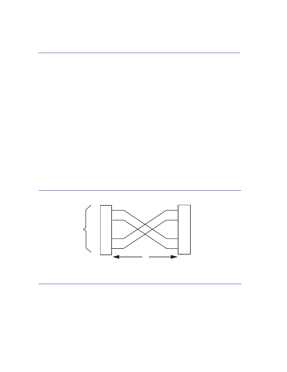
Figure 3-8
Four-Wire Crossover Cable RJ45 Pinouts for 10/100BASE-TX
RJ45 device port
RJ45-to-RJ45 crossover cable
Other device port
RX+/RX- and TX+/TX- connections.
These connections must share a common color pair.
TX+
TX
RX+
RX 2
1
3
6
TX+
TX
2
1
3
6
36771_21
RX+
RX
А
Б
В
Г