Kichler 43348 User Manual
Kichler Lighting
30) Make wire connections (connectors not provided.) Reference chart below for
correct connections and wire accordingly.
31) Push fixture to ceiling, carefully passing mounting screws through holes in
canopy.
32) Thread knurl knobs onto mounting screws. Tighten knurl knobs to secure
fixture to ceiling.
CABLE LENGTH ADJUSTMENT INSTRUCTIONS
1) Adjust the length of the cables to achieve the desired height of the mounted
fixture. (See cable adjustment detail)
To raise fixture: Push cable up into canopy. Release cable and cable will lock
into place.
To lower fixture: Push button in on cable adjuster and pull cable down.
Release button to lock cable in place.
NOTE: With button pushed in cable will raise and lower. Without button
pushed in cable will only raise up and lock in place.
1) Lower bar with socket clusters down through top of outer shade.
2) Place outer shade with bar over inner shade.
3) Align holes at each end of bar with holes in each bracket on inside of inner
shade.
4) Thread screws down through each hole in bar and into holes in brackets.
Tighten screws to secure inner shade in place.
5) Insert recommended bulbs.
6) Thread one small threaded pipe into each stem on the bottom of each socket
cluster.
7) Thread one hexnut onto end of each threaded pipe.
8) Slip one flat washer then one rubber washer over end of each threaded pipe.
9) Raise diffuser up to fixture. Pass holes in diffuser over end of each threaded
pipe.
10) Slip one rubber washer then one flat washer over end of each threaded pipe.
Thread one hexnut onto end of each threaded pipe
11) Thread one finial onto end of each threaded pipe. Tighten finials to secure
diffuser in place. (DO NOT over tighten.)
12) Determine the amount of stems necessary to achieve desired height of
fixture.
CAUTION: At least one 6" stem must be used.
13) Pass fixture wire from each coupling on bar through each stem and screw
each stem to coupling on top of bar. NOTE: Thread locking compound must
be applied to all stem threads as noted with symbol (3) to prevent accidental
rotation of fixture during cleaning, relamping, etc.
14) Pass fixture wire through each remaining stems and screw remaining stems
together.
15) After desired number of stems are assembled to fixture, shorten the cables
just until taut. Refer to Cable Length Adjustment Instructions below.
NOTE: Fixture may be hung with or without loops and chain link.
With loops and chain link:
16) Thread one small threaded pipe into end of each small loop.
17) Pass fixture wire from one last stem up through threaded pipe in end of
one small loop. Thread that small loop onto the end of stem.
18) Repeat step 17 for other last stem.
19) Attach one chain link to each small loop at end of each last stem.
20) Attach one small loop to end of each chain link.
21) Pass fixture wire through hole in second small loop.
22) Pass fixture wire from each small loop through each hole in canopy. Lower
canopy down over stems. Pass holes in canopy over each threaded pipe at
end of each small loop.
23) Pass fixture wire through each hole in canopy cover. Lower canopy cover
down into canopy. Pass threaded pipes from inside canopy through holes
in canopy cover.
24) From each small threaded pipe protruding from top of canopy cover pass
fixture wire through hole in one lockwasher. Thread each lockwasher onto
end of each threaded pipe.
25) Pass fixture wire through hole in each hexnut. Thread each hexnut onto end
of each threaded pipe.
FOLLOW STEPS 26-32 TO COMPLETE INSTALLATION.
Without loops and chain link:
16) Pass fixture wire from end of each last stem through one small threaded pipe.
Thread one small threaded pipe into end of each last stem.
17) Pass fixture wire through holes in canopy. Lower canopy down and pass
holes in canopy over each end of threaded pipe on stems.
18) Pass fixture wire through each hole in canopy cover. Lower canopy cover
down into canopy. Pass threaded pipes from inside canopy through holes
in canopy cover.
19) From each small threaded pipe protruding from top of canopy cover pass
fixture wire through hole in one lockwasher. Thread each lockwasher onto
end of each threaded pipe.
20) Pass fixture wire through hole in each hexnut. Thread each hexnut onto end
of each threaded pipe.
FOLLOW STEPS 26-32 TO COMPLETE INSTALLATION.
26) TURN OFF POWER.
IMPORTANT: Before you start, NEVER attempt any work without shutting off
the electricity until the work is done.
a) Go to the main fuse, or circuit breaker, box in your home. Place the main
power switch in the “OFF” position.
b) Unscrew the fuse(s), or switch “OFF” the circuit breaker switch(s), that
control the power to the fixture or room that you are working on.
c) Place the wall switch in the “OFF” position. If the fixture to be replaced
has a switch or pull chain, place those in the “OFF” position.
27) Find the appropriate threaded holes on mounting strap. Assemble mounting
screws into threaded holes.
28) Attach mounting strap to outlet box. (Screws provided). Mounting strap can be
adjusted to suit position of fixture.
29) Grounding instructions: (See Illus. A or B).
A) On fixtures where mounting strap is provided with a hole and two raised
dimples. Wrap ground wire from outlet box around green ground screw, and
thread into hole.
B) On fixtures where a cupped washer is provided. Attach ground wire from
outlet box under cupped washer and green ground screw, and thread into
mounting
strap.
If fixture is provided with ground wire. Connect fixture ground wire to outlet
box ground wire with wire connector. (Not provided.) After following the above
steps. Never connect ground wire to black or white power supply wires.
GREEN GROUND
SCREW
CUPPED
WASHER
A
B
OUTLET BOX
GROUND
FIXTURE
GROUND
DIMPLES
WIRE CONNECTOR
(NOT PROVIDED)
OUTLET BOX
GROUND
GREEN GROUND
SCREW
FIXTURE
GROUND
Connect Black or
Red Supply Wire to:
Connect
White Supply Wire to:
Black
White
*Parallel cord (round & smooth)
*Parallel cord (square & ridged)
Clear, Brown, Gold or Black
without tracer
Clear, Brown, Gold or Black
with tracer
Insulated wire (other than green)
with copper conductor
Insulated wire (other than green)
with silver conductor
*Note: When parallel wires (SPT I & SPT II)
are used. The neutral wire is square shaped
or ridged and the other wire will be round in
shape or smooth (see illus.)
Neutral Wire
Date Issued: 8/1/14
IS-43348-US
SEE OTHER SIDE FOR SPANISH TRANSLATIONS.
VEA EL OTRO LADO DE TRADUCCIONES AL ESPAÑOL.
We’re here to help
866-558-5706
Hrs: M-F 9am to 5pm EST
PRESSED
CABLE ADJUSMENT DETAIL
EL DETALLE DE AJUSTE DEL CABLE
NOT
PRESSED
UP & DOWN
UP ONLY
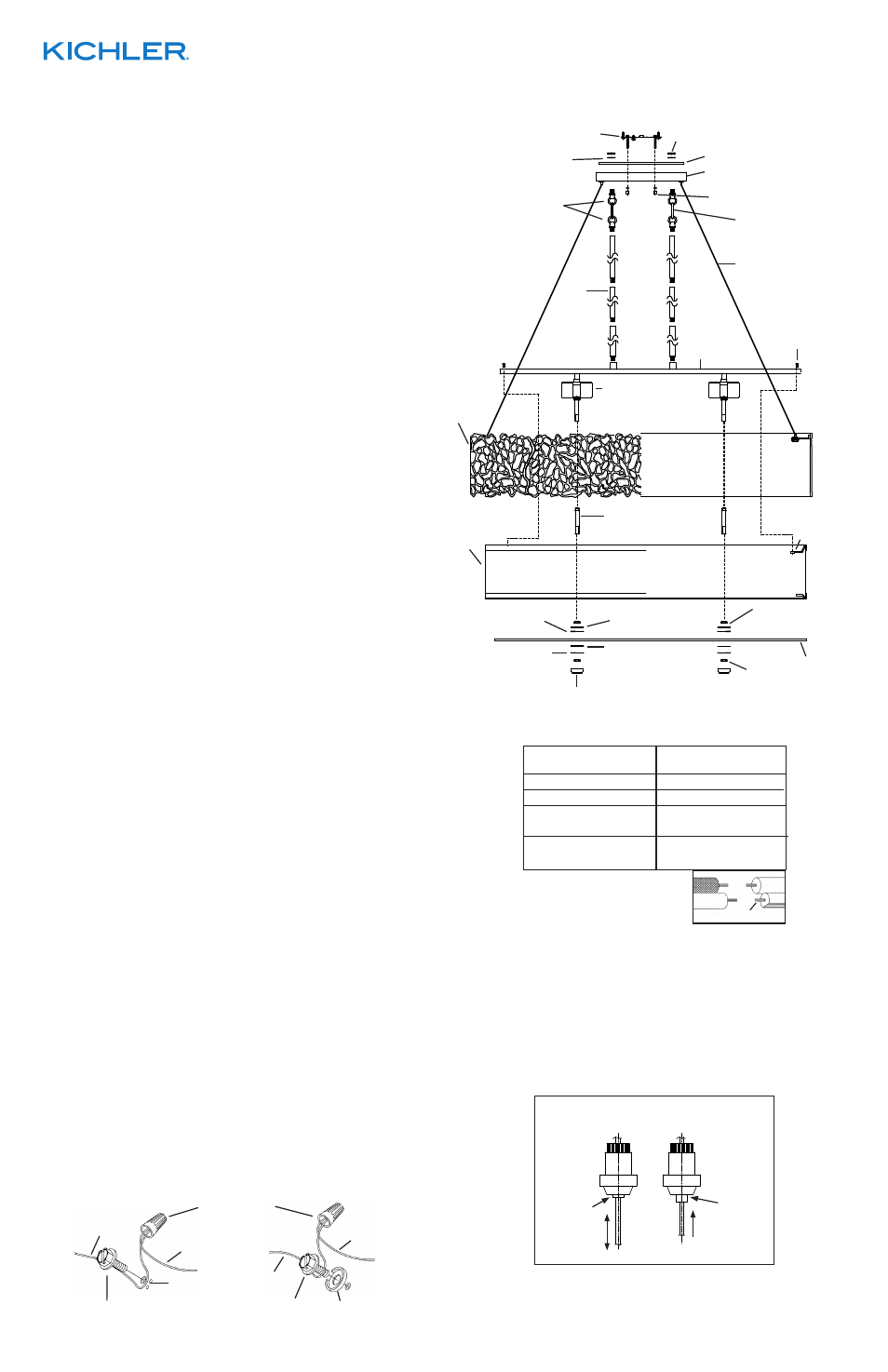
MOUNTING STRAP
ABRAZADERA DE MONTAJE
CANOPY
ESCUDETE
KNURL KNOB
PERILLA ESTRADA
THREADED PIPE
TUBO ROSCADO
FINIAL
CAPUCHON
HEXNUT
TUERCA
HEXAGONAL
RUBBER WASHER
ARANDELA DE
CAUCHO
FLAT WASHER
ARANDELA PLANA
DIFFUSER
DIFUSOR
OUTER SHADE
PANTALLA
EXTERNA
CABLE
CABLE
LOCKWASHER
ARANDELA DE SEGURIDAD
HEXNUT
TUERCA HEXAGONAL
STEM
VÁSTAGO
3
3
3
BAR
BARRA
SCREW
TORNILLO
INNER SHADE
PANTALLA
INTERNA
HEXNUT
TUERCA
HEXAGONAL
LOOP
ANILLO
CANOPY COVER
CUBIERTA DEL ESCUDETE
BRACKET
SOPORTE
3
RUBBER WASHER
ARANDELA DE
CAUCHO
FLAT WASHER
ARANDELA PLANA
SOCKET CLUSTER
GRUPO DE
PORTALÁMPARAS
CHAIN LINK
ESLABÓN DE CADENA