Kichler 42482 User Manual
Kichler Lighting
1) Lower one half of glare shield down onto bracket, aligning holes in glare shield with holes in
bracket.
2) Set retaining plate on top of glare shield, aligning holes in plate with holes in glare shield.
3) Thread ball studs into holes in retaining plate and into glare shield. (DO NOT over tighten.)
4) Repeat steps 1, 2 and 3 for remaining half of glare shield.
5) Set shade down over fixture body passing hole in bracket on shade over coupling on top of fixture
body.
6) Screw end of long threaded pipe with hexnut into coupling on top of fixture body.
7) Slip short tube then check ring down over threaded pipe.
8) Pass center column down over long threaded pipe.
9) Slip second check ring then long tube down over threaded pipe.
10) Pass third check ring down over end of threaded pipe and thread loop onto end of threaded pipe.
11) TuRN Off POweR.
IMPORTANT: Before you start, NeVeR attempt any work without shutting off the electricity until
the work is done.
a)
Go to the main fuse, or circuit breaker, box in your home. Place the main power switch in
the “Off” position.
b)
unscrew the fuse(s), or switch “Off” the circuit breaker switch(s), that control the power to
the fixture or room that you are working on.
c)
Place the wall switch in the “Off” position. If the fixture to be replaced has a switch or pull
chain, place those in the “Off” position.
12) Take threaded pipe from parts bag and screw in screw collar loop a minimum of 6mm (1/4”). Lock
into place with hexnut.
13) Run another hexnut down threaded pipe almost touching first hexnut. Now screw threaded pipe
into mounting strap. Mounting strap must be positioned with extruded thread faced into outlet box.
Threaded pipe must protrude out the back of mounting strap. Screw third hexnut onto end of
threaded pipe protruding from back of mounting strap.
14) unscrew the threaded ring from screw collar loop. Take canopy and pass over screw collar loop.
Approximately one half of the screw collar loop exterior threads should be exposed. Adjust screw
collar loop by turning assembly up or down in mounting strap. Remove canopy.
15) After desired position is found, tighten top hexnut up against the bottom of the mounting strap.
16) Slip canopy over screw collar loop and thread on threaded ring. Attach chain (with fixture
connected) to bottom of screw collar loop. unscrew threaded ring, let canopy and threaded ring
slip down.
17) weave electrical wire and ground wire through chain links no more than 3 inches apart. Pass wire
through threaded ring, canopy, screw collar loop, threaded pipe and into outlet box.
18) Grounding instructions: (See Illus. A or B).
A)
On fixtures where mounting strap is provided with a hole and two raised dimples. wrap
ground wire from outlet box around green ground screw, and thread into hole.
B)
On fixtures where a cupped washer is provided. Attach ground wire from outlet box under
cupped washer and green ground screw, and thread into mounting strap.
If fixture is provided with ground wire. Connect fixture ground wire to outlet box ground wire with
wire connector (not provided.) after following the above steps. Never connect ground wire to black
or white power supply wires.
19) Make wire connections (connectors not provided). Reference chart below for correct connections and
wire accordingly.
20) Raise canopy to ceiling.
21) Secure canopy in place by tightening threaded ring onto screw collar loop.
22) Slip flat washer then rubber washer over threaded pipe on end of adjustable pipe.
23) Raise diffuser up to fixture passing hole in diffuser over end of threaded pipe.
24) Slip rubber washer then flat washer over threaded pipe and screw hexnut onto end of threaded
pipe. (DO NOT over tighten.)
25) Pass large bottom trim, small bottom trim piece then crystal over threaded pipe and screw finial
onto threaded pipe. (DO NOT over tighten.)
NOTE: After assembly, if fixture does not hang straight, remove glass and bend adjustable pipe to
desired position, then reassemble glass.
CAUTION: DO NOT attempt to straighten fixture by pulling
on glass while glass is still assembled to fixture.
1) Baje la mitad de la pantalla antideslumbrante en la correa, alineando los agujeros en la pantalla
antideslumbrante con los agujeros en la correa.
2) fije la placa de retención en la parte superior de las pantallas antideslumbrantes, alineando los
agujeros en la placa con los agujeros en la pantalla antideslumbrante.
3) Rosque los espárragos de cabeza esférica en los agujeros de la placa de retención y en la
pantalla antideslumbrante. (NO apriete excesivamente.)
4) Repita los pasos 1, 2 y 3 para la mitad restante de la placa antideslumbrante.
5) Coloque la pantalla abajo encima del cuerpo del artefacto pasando el agujero en el soporte en la
pantalla, encima del acoplamiento en la parte superior del cuerpo del artefacto.
6) Atornille el extremo del tubo roscado con la tuerca hexagonal en el acoplamiento en la parte
superior del cuerpo del artefacto.
7) Resbale el tubo corto, luego el anillo de seguridad abajo, encima del tubo roscado.
8) Pase la columna central abajo, encima del tubo roscado largo.
9) Resbale el segundo anillo de seguridad, luego el tubo largo abajo, encima del tubo roscado.
10) Pase el tercer anillo de seguridad abajo, encima del extremo del tubo roscado y rosque el lazo en
el extremo del tubo roscado.
11) APAGue LA ALIMeNTACIóN eLéCTRICA.
IMPORTANTE: Antes de comenzar, NuNCA trate de trabajar sin antes desconectar la corriente
hasta que el trabajo se termine.
a)
Vaya a la caja principal de fusibles, o interruptor o caja de circuitos de su casa. Coloque el
interruptor de la corriente principal en posición de apagado “Off”.
b)
Desatornille el (los) fusible (s), o coloque el interruptor o interruptores del breaker en
posición de apagado “Off”, que controla (n) la corriente hacia el artefacto o habitación
donde está trabajando.
c) Coloque el interruptor de pared en posición de apagado “Off”. Si el artefacto que se va a
reemplazar tiene un interruptor o cadena que se jala, colóquelos en la posición de apagado
“Off”.
12) Tome el tubo roscado de la bolsa de piezas y atornille en el ojal de collar roscado un mínimo de 6 mm.
(1/4”). Inmovilice en el lugar con la tuerca hexagonal.
13) Instale otra tuerca hexagonal en el tubo roscado casi tocando la primera tuerca hexagonal.
Ahora, atornille el tubo roscado en la abrazadera de montaje. La abrazadera de montaje se debe
colocar con la rosca extruida mirando hacia la caja de salida. el tubo roscado debe sobresalir
atrás de la abrazadera de montaje. Atornille la tercera tuerca hexagonal en el extremo del tubo
roscado que sobresale de la parte posterior de la abrazadera de montaje.
14) Destornille el anillo roscado del ojal de collar roscado. Tome el escudete y pase sobre el ojal de
collar roscado. Aproximadamente la mitad de las roscas exteriores del ojal de collar roscado deben
estar expuestas. Ajuste el ojal del collar roscado
girando el conjunto arriba o abajo en la abrazadera de montaje. Quite el escudete.
15) Después de encontrar la posición deseada, apriete la tuerca hexagonal superior contra la inferior
de la abrazadera de montaje.
GReeN GROuND
SCRew
CuPPeD
wASHeR
A
B
OuTLeT BOX
GROuND
fIXTuRe
GROuND
DIMPLeS
wIRe CONNeCTOR
(NOT PROVIDeD)
OuTLeT BOX
GROuND
GReeN GROuND
SCRew
fIXTuRe
GROuND
Connect Black or
Red Supply Wire to:
Connect
White Supply Wire to:
Black
White
*Parallel cord (round & smooth)
*Parallel cord (square & ridged)
Clear, Brown, Gold or Black
without tracer
Clear, Brown, Gold or Black
with tracer
Insulated wire (other than green)
with copper conductor
Insulated wire (other than green)
with silver conductor
*Note: When parallel wires (SPT I & SPT II)
are used. The neutral wire is square shaped
or ridged and the other wire will be round in
shape or smooth (see illus.)
Neutral Wire
Date Issued: 8/21/09
IS-42482-uS
GLASS DIffuSeR
DIfuSOR
16) Resbale el escudete sobre el ojal de collar roscado y rosque en el anillo roscado. Acople la
cadena (con el artefacto conectado) a la parte inferior del ojal de collar roscado. Destornille el
anillo roscado, deje que el escudete y el anillo roscado resbalen hacia abajo.
17) Pase el alambre eléctrico y el alambre de tierra a través de los eslabones de la cadena, con una
separación de 3 pulgadas máxima. Pase el alambre a través del anillo roscado, del escudete, del
ojal de collar roscado, del tubo roscado y en la
caja de salida.
18) Instrucciones de conexión a tierra solamente para los estados unidos. (Vea la ilustracion A o B).
A) en las lámparas que tienen el fleje, de montaje con un agujero y dos hoyue los realzados.
enrollar el alambre a tierra de la caja tomacorriente alrededor del tornillo verde y pasarlo
por el aquiero.
B) en las lámparas con una arandela acopada. fijar el alambre a tierra de la caja tomacorriente
del ajo de la arandela acoada y tornillo verde, y paser por el fleje de montaje.
Si la lámpara viene con alambre a tierra. Conecter el alambre a tierra de la lámpara al alambre a
tierra de la caja tomacorriente con un conector de alambres (no incluido) espués de seguir los
pasos anteriores. Nunca conectar el alambra a tierra a los alambres eléctros negro o blanco.
19) Haga les conexiones de los alambres (no se proveen los connectores.) La tabla de referencia de
abajo indica las conexiones correctas y los alambres correspondientes.
20) Levante el escudete al cielo raso.
21) Sujete el escudete en el lugar apretando el anillo roscado en el ojal de collar roscado.
22) Resbale la arandela plana, luego la arandela de caucho encima del tubo roscado.
23) Levante el difusor hasta el artefacto pasando el agujero en el difusor encima del extremo del tubo
roscado.
24) Resbale la arandela de caucho, luego la arandela plana encima del tubo roscado y atornille la
tuerca hexagonal en el extremo del tubo roscado. (NO apriete excesivamente.)
25) Pase la guarnición inferior grande, la pieza de guarnición inferior pequeña, luego el cristal encima
del tubo roscado y atornille el capuchón en el tubo roscado. (NO apriete excesivamente.)
NOTA: Después del montaje, si el artefacto no cuelga recto, quite el vidrio y doble el tubo ajustable a
la posición deseada, luego vuelva a montar el vidrio.
PRECAUCIÓN: NO intente enderezar el
artefacto estirando del vidrio mientras el vidrio está todavía montado al artefacto.
ARANDeLA
CONCAVA
A
B
TIeRRA De LA
CAjA De SALIDA
TORNILLO De TIeRRA,
VeRDe
DePReSIONeS
TIeRRA
ARTefACTO
CONeCTOR De ALAMBRe
(NO Se PROVee)
TIeRRA De LA
CAjA De SALIDA
TORNILLO De TIeRRA,
VeRDe
TIeRRA
ARTefACTO
Conectar el alambre de
suministro negro o rojo al
Conectar el alambre de
suministro blanco al
Negro
Blanco
*Cordon paralelo (redondo y liso) *Cordon paralelo (cuadrado y estriado)
Claro, marrón, amarillio o negro
sin hebra identificadora
Claro, marrón, amarillio o negro
con hebra identificadora
Alambre aislado (diferente del verde)
con conductor de cobre
Alambre aislado (diferente del
verde) con conductor de plata
*Nota: Cuando se utiliza alambre paralelo
(SPT I y SPT II). El alambre neutro es de forma
cuadrada o estriada y el otro alambre será de
forma redonda o lisa. (Vea la ilustracíón).
Hilo Neutral
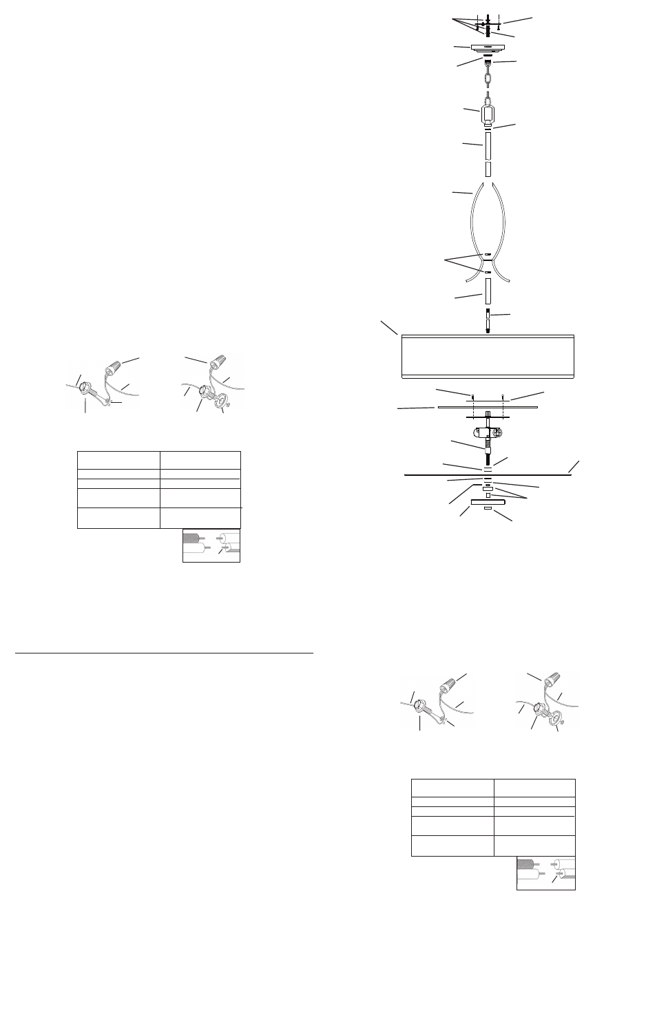
MOuNTING STRAP
ABRAzADeRA De
MONTAje
HeXNuT
TueRCA
HeXAGONAL
THReADeD PIPe
TuBO ROSCADO
SCRew COLLAR LOOP
OjAL De COLLAR
ROSCADO
CANOPY
eSCuDeTe
THReADeD RING
ANILLO ROSCADO
LOOP
LAzO
fINIAL
CAPuCHON
RuBBeR wASHeR
ARANDeLA De CAuCHO
fLAT wASHeR
ARANDeLA PLANA
RuBBeR wASHeR
ARANDeLA De CAuCHO
fLAT wASHeR
ARANDeLA PLANA
BOTTOM TRIM
GuARNICIóN
INfeRIOR
ADjuSTABLe PIPe
TuBO AjuSTABLe
CRYSTAL
CRISTAL
HeXNuT
TueRCA HeXAGONAL
THReADeD PIPe
TuBO ROSCADO
SHORT TuBe
TuBO CORTO
LONG TuBe
TuBO LARGO
CHeCK RING
ANILLO De SeGuRIDAD
GLARe SHIeLD
PLACA ANTIDeSLuMBRANTe
ReTAINING PLATe
PLACA De ReTeNCIóN
BALL STuD
eSPáRRAGO De CABezA
eSféRICA
SHADe
PANTALLA
CHeCK RING
ANILLO De SeGuRIDAD
CeNTeR COLuMN
COLuMNA CeNTRAL