Kichler 42051 User Manual
Page 2
MounTInG STrAp
ABrAzADerA De MonTAje
1) Set top trim on top of fixture body.
2) Screw loop onto threaded pipe protruding from inside top trim.
3) Turn off power.
IMPORTANT: Before you start, neVer attempt any work without
shutting off the electricity until the work is done.
a)
Go to the main fuse, or circuit breaker, box in your home. place the main
power switch in the “off” position.
b)
unscrew the fuse(s), or switch “off” the circuit breaker switch(s), that
control the power to the fixture or room that you are working on.
c)
place the wall switch in the “off” position. If the fixture to be replaced has
a switch or pull chain, place those in the “off” position.
4) Assemble mounting screws into threaded holes in mounting strap.
5) Attach mounting strap to outlet box. (Screws not provided).
6) Grounding instructions: (See Illus. A or B).
A) on fixtures where mounting strap is provided with a hole and two raised
dimples. wrap ground wire from outlet box around green ground screw, and
thread into hole.
B)
on fixtures where a cupped washer is provided. Attach ground wire from
outlet box under cupped washer and green ground screw, and thread into
mounting strap.
If fixture is provided with ground wire. Connect fixture ground wire to outlet box
ground wire with wire connector. (not provided.) After following the above steps.
never connect ground wire to black or white power supply wires.
7) Make wire connections (connectors not provided.) reference chart below for correct
connections and wire accordingly.
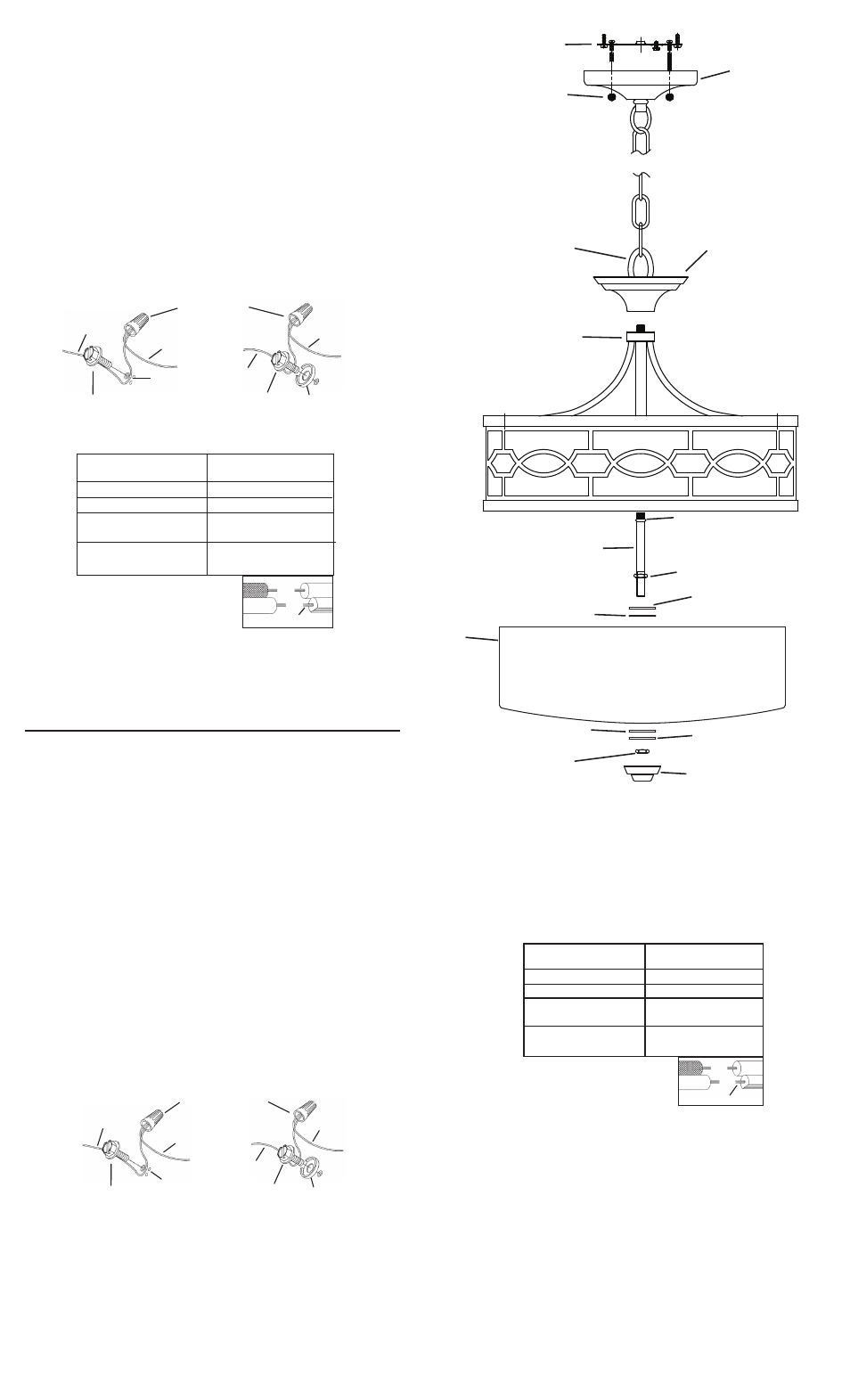
8) push fixture to ceiling, carefully passing mounting screws through holes in canopy.
9) Secure fixture to ceiling with knurl knobs.
10) Screw short end of threaded pipe with bead into coupling at bottom of fixture.
11) Slip flat washer then rubber washer over threaded pipe.
12) raise glass up to fixture carefully passing threaded pipe through hole in glass.
13) Slip rubber washer then flat washer over end of threaded pipe.
14) Screw hexnut then finial onto threaded pipe. (Do noT over tighten.)
1) Coloque la guarnición superior en la parte superior del cuerpo del artefacto.
2) Atornille el lazo en el tubo roscado que sobresale del interior de la guarnición
superior
3) ApAGue lA AlIMenTACIón eléCTrICA.
IMPORTANTE: Antes de comenzar, nunCA trate de trabajar sin antes desconectar
la corriente hasta que el trabajo se termine.
a)
Vaya a la caja principal de fusibles, o interruptor o caja de circuitos de su
casa. Coloque el interruptor de la corriente principal en posición de
apagado “off”.
b)
Desatornille el (los) fusible (s), o coloque el interruptor o interruptores del
breaker en posición de apagado “off”, que controla (n) la corriente hacia
el artefacto o habitación donde está trabajando.
c) Coloque el interruptor de pared en posición de apagado “off”. Si el
artefacto que se va a reemplazar tiene un interruptor o cadena que se jala,
colóquelos en la posición de apagado “off”.
4) Monte los tornillos de montaje en los agugerjos roscados, en la abrazadera de
montaje.
5) una la abrazadera de montaje a la caja de salida. (no se provee tornillos).
6) Instrucciones de conexión a tierra solamente para los estados unidos.
(Vea la ilustracion A o B).
A) en las lámparas que tienen el fleje, de montaje con un agujero y dos hoyue
los realzados. enrollar el alambre a tierra de la caja tomacorriente alrededor
del tornillo verde y pasarlo por el aquiero.
B)
en las lámparas con una arandela acopada. fijar el alambre a tierra de la
caja tomacorriente del ajo de la arandela acoada y tornillo verde, y paser por
el fleje de montaje.
Si la lámpara viene con alambre a tierra. Conecter el alambre a tierra de la lámpara
al alambre a tierra de la caja tomacorriente con un conector de alambres (no
incluido) espués de seguir los pasos anteriores. nunca conectar el alambra a
tierra a los alambres eléctros negro o blanco.
Green GrounD
SCrew
CuppeD
wASHer
A
B
ouTleT BoX
GrounD
fIXTure
GrounD
DIMpleS
wIre ConneCTor
(noT proVIDeD)
ouTleT BoX
GrounD
Green GrounD
SCrew
fIXTure
GrounD
Connect Black or
Red Supply Wire to:
Connect
White Supply Wire to:
Black
White
*Parallel cord (round & smooth)
*Parallel cord (square & ridged)
Clear, Brown, Gold or Black
without tracer
Clear, Brown, Gold or Black
with tracer
Insulated wire (other than green)
with copper conductor
Insulated wire (other than green)
with silver conductor
*Note: When parallel wires (SPT I & SPT II)
are used. The neutral wire is square shaped
or ridged and the other wire will be round in
shape or smooth (see illus.)
Neutral Wire
Date Issued: 5/7/10
IS-42051-uS
7) Haga les conexiones de los alambres (no se proveen los connectores.) la tabla
de referencia de abajo indica las conexiones correctas y los alambres correspondientes.
8) empuje el artefacto hacia el techo, pasando cuidadosamente los tornillos de
montaje a través de los orificios en el escudete.
9) Asegure el artefacto al techo con las perillas estriadas.
10) Atornille el extremo corto del tubo roscado con aislador de cuenta en el
acoplamiento en la parte inferior del artefacto.
11) resbale la arandela plana, luego la arandela de caucho encima del tubo roscado.
12) levante el vidrio arriba al artefacto pasando cuidadosamente el tubo roscado a
través del agujero en el vidrio.
13) resbale la arandela de caucho, luego la arandela plana encima del tubo roscado.
14) Atornille la tuerca hexagonal, luego el capuchón al tubo roscado. (no apriete
ArAnDelA
ConCAVA
A
B
TIerrA De lA
CAjA De SAlIDA
TornIllo De TIerrA,
VerDe
DepreSIoneS
TIerrA
ArTefACTo
ConeCTor De AlAMBre
(no Se proVee)
TIerrA De lA
CAjA De SAlIDA
TornIllo De TIerrA,
VerDe
TIerrA
ArTefACTo
Conectar el alambre de
suministro negro o rojo al
Conectar el alambre de
suministro blanco al
Negro
Blanco
*Cordon paralelo (redondo y liso) *Cordon paralelo (cuadrado y estriado)
Claro, marrón, amarillio o negro
sin hebra identificadora
Claro, marrón, amarillio o negro
con hebra identificadora
Alambre aislado (diferente del verde)
con conductor de cobre
Alambre aislado (diferente del
verde) con conductor de plata
*Nota: Cuando se utiliza alambre paralelo
(SPT I y SPT II). El alambre neutro es de forma
cuadrada o estriada y el otro alambre será de
forma redonda o lisa. (Vea la ilustracíón).
Hilo Neutral
CAnopY
eSCuDeTe
fIXTure BoDY
Cuerpo Del
ArTefACTo
Knurl KnoB
perIllA eSTrADA
THreADeD pIpe
TuBo roSCADo
HeXnuT
TuerCA HeXAGonAl
GlASS
VIDrIo
fInIAl
CApuCHon
BeAD
AISlADor
ruBBer wASHer
ArAnDelA De CAuCHo
flAT wASHer
ArAnDelA plAnA
HeXnuT
TuerCA HeXAGonAl
flAT wASHer
ArAnDelA plAnA
ruBBer wASHer
ArAnDelA De CAuCHo
SEE REvERSE SIdE fOR SEMI fluSh INSTAl-
lATION INSTRucTIONS.
lEA EN lA PARTE TRASERA lAS INSTRuc-
cIONES PARA lA INSTAlAcIóN EN El TEchO.
Top TrIM
GuArnICIón
SuperIor
loop
lAzo