Kichler 2220 User Manual
Page 2
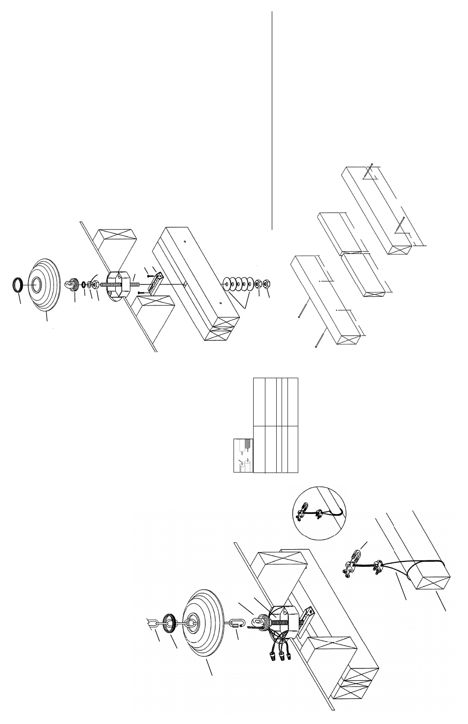
IS-2220-CB
N
MEANS OF SUPPOR
T MUST BE ERECTED ABOVE OUTLET BOX. BELOW IS ONE SUGGESTED METHOD FOR
JOIST 16” ON CENTER WITH FIXTURE CENTERED BETWEEN JOISTS, AS SHOWN
1
5
)
T
o
erect means of support four pieces of lumber will be required (not included).
T
w
o
2x4’
s at min. of 19" long.
T
w
o
1x4’
s at min.9 1/4" long.
16)
Lay one 2x4 on flat surface suitable and stable for nailing.
17)
Lay the two 1x4’
s on 2x4 allowing 1/2" gap between ends of 1x4’
s at center
.
1
8
)
Lay remaining 2x4 on top of 1x4’
s and nail pieces together using 3 1/8" long12d nails (not included) on center
at approximately 3" from each end.
1
9
)
T
urn assembled lumber over and nail two more nails in at approximately
6
"
from each end.
20)
T
urn of
f power
.
21)
If fixture is provided with a safety cable it must pass through outlet box.
Drill 3/16” diameter hole in outlet box if no other holes are available.
22)
Remove knockout in top of outlet box.
2
3
)
Align hole in mounting strap (D) with gap between 1x4’
s and secure to 2x4’
s
using provided #10 sheet metal screws (Z).
24)
In area above outlet box lay assembled lumber from steps 1-5
over ceiling joist (with mounting strap down) aligning gap between
1x4’
s with knockout
removed in outlet box.
25)
Screw hexnut (H) onto threaded rod (P).
26)
Slip ground lug (F) and lockwasher (J) onto threaded rod (P).
2
7
)
Thread screw collar loop (L) onto threaded rod (P) until threaded pipe
is flush with hole on lower side of screw collar loop or threaded rod bottoms out.
28)
Secure screw collar loop (L) in place by tightening hexnut (H) down against
ground lug (F), lockwasher (J) and screw collar loop.
29)
T
emporarily slip canopy (M) over screw collar loop (L).
Approximately one
half of the screw collar loop exterior threads should be exposed below canopy
.
30)
T
emporarily screw threaded ring (N) onto screw collar loop (L).
31)
In area above outlet box pull up on threaded rod (P) until canopy is snug against ceiling.
3
2
)
Slide flat washers (X)
down threaded rod and against top of lumber assembly
. Secure in
place
b
y
r
u
n
n
in
g
j
a
m
nuts (Q & R) down against flat washer
.
33)
Secure lumber assembly in place by toe-nailing or other means.
34)
T
ighten anti-rotational screw located next to center hole inside mounting strap (D) with provided wrench.
35)
Remove threaded ring (N) and canopy (M).
W
ARNING: TO ENSURE PERSONAL SAFETY AND TO PREVENT DAMAGE TO YOUR HOME CON-
SUL
T A QUALIFIED BUILDER OR ARCHITECT BEFORE INST
ALLING A FIXTURE HEA
VIER THAN
50 LBS. TO THE JOIST OR TRUSS SYSTEM OF YOUR HOME.
F
M
N
D
Z
H
J
P
L
19
3
3
9
1/4
9
1/4
6
X
R
Q
2
36)
Attach chain to fixture. Fixture loop has one chain link factory installed.
Chain has one locking link at each end. Unscrew coupling on locking
link and slip over link attached to loop. Screw coupling closed.
37)
Slip threaded ring (N) then canopy (M) onto chain (W)
38)
Attach chain (with fixture connected) to bottom of screw collar
loop following the same procedure as in step 1.
39)
W
eave electrical wire, ground wire and safety cable through
chain links no m0re than 3 inches apart.
40)
Pass electrical wire ground wire and safety cable
through threaded ring (N), canopy (M), one of the
slots in screw collar loop (L) and into outlet box.
41)
Pass safety cable through hole (See sec. 1)
42)
In area above outlet box
wrap cable around one
of the 2 x 4’
s erected in section 1 and pull cable taut..
43)
Secure cable with (2) clamps provided.
NOTE: Cable is not to be used as the only means of
fixtur
e support. Please follow independent mounting
instructions completely
.
44)
Connect fixture ground wire and ground wire attached
to threaded rod (B or P) to outlet box ground
wire with wire connector (not provided).
Never connect ground wire to black or
white power supply wires.
45)
Make wire connections (connectors
not provided). Reference chart below
for correct connections and wire
accordingly
.
46)
Raise canopy (M) to ceiling.
47)
Secure canopy (M) in place by screwing
threaded ring (N) onto screw collar loop (L)
48) Scr
ew bottom trim onto bottom of fixtur
e.
49)
Slip glass over socket at end of arm and secure in place with
socket ring.
B or P
L
X
M
N
W
3
Connect Black or
Red Supply Wire to:
Connect
White Supply Wire to:
Black
White
*Parallel cord (round & smooth)
*Parallel cord (square & ridged)
Clear
, Brown, Gold or Black
without tracer
Clear
, Brown, Gold or Black
with tracer
Insulated wire (other than green)
with copper conductor
Insulated wire (other than green)
with silver conductor
*Note: When parallel wires (SPT I & SPT II)
are used. The neutral wire is square shaped
or ridged and the other wire will be round in
shape or smooth (see illus.)
Neutral Wire
SAFETY
CABLE
CABLE DE
APOYO
STRUCTURAL
BRIDGING
MEMBER
MIEMBRO DE CONEXIÓN
ESTRUCTURAL
CLAMP
GRAMP
A