Fig. 2a – Kichler 2218 User Manual
Page 2
M
S
P
CEILING JOIST
SOLIVES DE
PLAFOND
2 X 4
1B
N
D
L
A
C
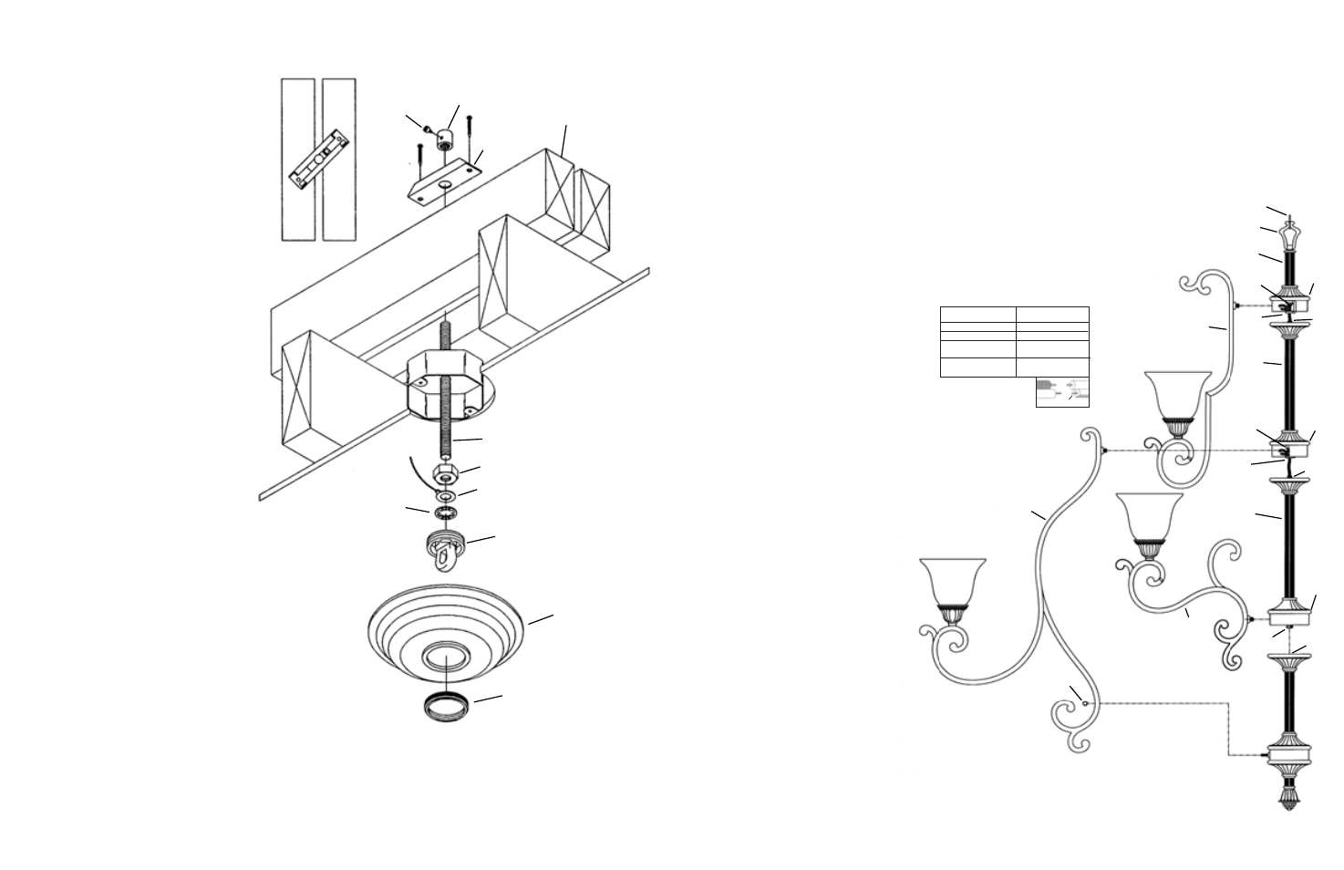
MOUNTING TO A STANDARD OUTLET BOX
MEANS OF SUPPORT MUST BE ERECTED ABOVE OUTLET BOX. BELOW IS ONE SUG-
GESTED METHOD.
1) Screw threaded rod (P) from parts bag into pipe coupling (A) until threaded pipe is flush with
top of pipe coupling. Secure in place by tightening allen head screw (C) with provided wrench.
2) Slip mounting strap (D) over provided 1/2-13UNC threaded rod (P).
3) Remove knockout in top of outlet box.
4)
Support cable from fixture (see sec. 3) must pass through outlet box.
Drill 3/16” diameter hole in outlet box if no other holes are available.
5) In area above outlet box pass threaded rod (P) through hole in center
of outlet box.
6) Lay a 2x4 across ceiling joist on either side of threaded rod (P).
7) Secure 2x4’s in place by toe-nailing or other means.
8)
Screw hexnut (H) onto threaded rod (P).
9) Slip ground lug (F) and lockwasher (J) onto threaded rod (P).
10) Thread screw collar loop (L) onto threaded rod (P) until threaded
pipe is flush with hole on lower side of screw collar loop.
11) Secure screw collar loop (L) in place by tightening hexnut (H) down
against ground lug (F), lockwasher (J) and screw collar loop.
12) Temporarily slip canopy (M) over screw collar loop (L).
Approximately one half of the screw collar loop exterior
threads should be exposed below canopy.
13) Temporarily screw threaded ring (N) onto screw collar loop (L).
14) In area above outlet box pull up on threaded rod (P) until canopy
is snug against ceiling.
15) Slide mounting strap (D) down threaded rod (P) and against 2x4’s.
16) Screw pipe coupling (A) down threaded rod (P) until pipe coupling
is snug against mounting strap (D) and canopy (M) is snug against
ceiling.
17) Tighten allen head screw (C).
18) Secure mounting strap (D) in place by laying diagonally across both
2x4’s and driving two #10 x 1" sheet metal or equivalent screws (not
provided) through holes at ends of mounting strap. Tighten
anti-rotational hex screw located next to center hole inside
mounting strap (D) with provided allen wrench..
NOTE:
Mounting strap (D) must be secured to prevent rotation.
19) Remove threaded ring (N) and canopy (M).
F
J
H
2
IS-2218-CB
1) Pass safety cable from column (A) through hole in
bottom of hickey (B) and up through threaded pipe
(C) inside column (E). Do not assemble columns at
this time.
2) Pass safety cable from column (E) through hole in
bottom of hickey (G) and up through threaded pipe (I)
inside column (K). Do not assemble columns at this time.
3) Lay column sections on flat surface end to end.
Temporarily attach clamp (T) to safety cable approximately
24" above loop. This will prevent cable from slipping
out of columns and ease in assembly.
4) Attach chain (W) to bottom of screw collar loop (L).
Screw collar loop has one chain link factory installed.
Chain has one locking link (S) at each end. Unscrew
coupling on locking link and slip over link attached to
screw collar loop. Screw coupling closed.
5) Attach chain (W) to loop (V) at top of column (K).
6) Assemble arms (AA) to body (BB) at bottom of column
(K) using lockwashers and hexnuts (see Fig. 2A).
Tighten hexnuts using provided wrench.
7)
TOP TIER WIRING
A) Take one 28” black and one 28” white jumper wire
from parts bag and pass through hole in bottom of
hickey (G).
B) Connect 3 black socket wires, the black jumper
wire and the appropriate supply wire (reference
chart above) using provided wire connector.
Repeat for white wires.
CAUTION: Make sure all wires are stripped 5/8” (16
mm) and no loose wire strands are outside the con-
nectors. As an added precaution, slightly tug on each
wire to ensure that each on is secure inside wire con-
nector and then wrap the connection with electrical
tape.
8) Pass jumper wire through threaded pipe (C) inside
column (E). Pull jumper wires out the side of hickey (B).
9) Apply a small amount of thread locking compound to
threaded rod (C) and screw threaded rod into hickey
(G). Make sure all wires are tucked into body and do
not get pinched during assembly.
10) Assemble arms (CC) to body (DD) at bottom of column
(E) using lockwashers and hexnuts (see fig 2A).
Tighten hexnuts using provided wrench.
11)
MIDDLE TIER WIRING
A) Take two 6” black and two6” white jumper wires
from parts bag.
B) Connect one 6” black jumper to three black socket
wires. Connect the other black jumper wire to the
remaining three black socket wires using provided
connectors. Repeat for white wires.
C) Connect the two 6” black jumper wires to the black
jumper wire from column (E) and the black jumper
wire from column (A) using provided connectors.
Repeat for white wires.
CAUTION: Make sure all wires are stripped 5/8” (16
mm) and no loose wire strands are outside the con-
nectors. As an added precaution, slightly tug on each
wire to ensure that each on is secure inside wire con-
nector and then wrap the connection with electrical
tape.
12) Apply a small amount of thread locking compound to
threaded rod (EE) and screw threaded rod into hickey
(B). Make sure all wires are tucked into body and do
not get pinched during assembly.
13) Assemble large arms (JJ) to body (Y) using lock
washers and hexnuts (see Fig. 2A). Tighten hexnuts
using provided wrench.
14)
BOTTOM TIER WIRING
A) Take two 6” black and two6” white jumper wires
from parts bag.
B) Connect one 6” black jumper to three black socket
wires. Connect the other black jumper wire to the
remaining three black socket wires using provided
connectors. Repeat for white wires.
C) Connect the two 6” black jumper wires to the black
jumper wire from column (A) using provided
connectors. Repeat for white wires.
CAUTION: Make sure all wires are stripped 5/8” (16
mm) and no loose wire strands are outside the con-
nectors. As an added precaution, slightly tug on each
wire to ensure that each on is secure inside wire con-
nector and then wrap the connection with electrical
tape.
15) Apply a small amount of thread locking compound to
threaded rod (LL) and screw threaded rod into hickey
(FF). Make sure all wires are tucked into body (Y)
and do not get pinched during assembly.
16) Secure bottom of middle tier arms in place using ball
knobs (GG).
17) Remove clamp (T) assembled to safety cable in step 3.
18) Unscrew threaded ring (N) and allow threaded ring
and canopy (M) to drop down to expose outlet box.
19) Weave electrical wire, ground wire and safety cable
through chain links no more than 3 inches apart.
20) Pass electrical wire ground wire and safety cable
through threaded ring (N), canopy (M), one of the
slots in screw collar loop (L) and into outlet box.
21) Pass safety cable through hole (See sec. 1A or 1B)
22) In area above outlet box either:
A)
wrap cable around outlet box brace and pull
cable taunt.
or:
B)
wrap cable around one of the 2x4’s erected in
section 1B and pull cable taunt..
23) Secure cable with (2) clamps provided.
NOTE: Cable is not to be used as the only means
of fixture support. Please follow independent
mounting instructions completely.
24) Connect fixture ground wire and ground wire attached
to threaded rod (B or P) to outlet box ground wire with
wire connector (not provided). Never connect ground
wire to black or white power supply wires.
25) Make wire connections (connectors not provided).
Reference chart below for correct connections and
wire accordingly.
26) Raise canopy (M) to ceiling.
27) Secure canopy (M) in place by screwing
threaded ring (N) onto screw collar loop (L).
28) Slip glass over socket at end of arm and
secure in place with socket ring.
Connect Black or
Red Supply Wire to:
Connect
White Supply Wire to:
Black
White
*Parallel cord (round & smooth)
*Parallel cord (square & ridged)
Clear, Brown, Gold or Black
without tracer
Clear, Brown, Gold or Black
with tracer
Insulated wire (other than green)
with copper conductor
Insulated wire (other than green)
with silver conductor
*Note: When parallel wires (SPT I & SPT II)
are used. The neutral wire is square shaped
or ridged and the other wire will be round in
shape or smooth (see illus.)
Neutral Wire
W
K
G
E
B
A
V
I
C
BB
AA
CC
C
EE
JJ
LL
FF
GG
DD
FIG. 2A
Y