Warning – Emerson MAYA ZEN CF750ORB00 User Manual
Page 7
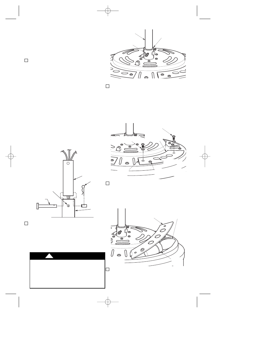
10. Unscrew and remove one lockwasher
and screw from each end of the upper
light plate cover on the fan motor
housing. Do not remove the screw
closest to the light holes (Figure 9).
NOTE: The screw closest to the light
holes, holds the light socket to the light
plate cover. Do not remove this screw.
11. Pull up on the upper light plate cover
to expose the light socket. Place a 7-
watt (maximum) candelabra base bulb
(not supplied) into the light socket
(Figure 10). Insert bulb into each of the
remaining three sockets.
12. Push the upper light plate cover down
for each of the four light sockets and
replace the lockwashers and screws
previously removed in Step 10.
7
8. Loosen the two setscrews in motor
coupling if necessary. Separate,
untwist and unkink the three 80” motor
leads. Route the motor lead wires
through the desired downrod. Align the
clevis pin holes in the downrod with the
holes in the motor coupling. Install the
clevis pin and secure with the hairpin
clip (Figure 7). The clevis pin must go
through the holes in the motor coupling
and the holes in the downrod. Be sure
to push the straight leg of the hairpin
clip through the hole near the end of
the clevis pin until the curved portion of
the hairpin clip snaps around the clevis
pin. The hairpin clip must be properly
installed to prevent the clevis pin from
working loose. Pull on the downrod to
make sure the clevis pin is properly
installed.
9. While pulling up on the downrod,
securely tighten the two setscrews in
the motor coupling (Figure 8).
NOTE: The two setscrews must be
properly installed as described above,
or fan wobble could result.
SETSCREW
CLEVIS PIN
MOTOR
COUPLING
DOWNROD
HAIRPIN
CLIP
DOWNROD
HAIRPIN
CLIP
MOTOR
COUPLING
SETSCREW (2)
CLEVIS PIN
Figure 7
REMOVE SCREW AND
LOCKWASHER
UPPER LIGHT
PLATE COVER
HINGE
DO NOT REMOVE LIGHT
SOCKET SCREW
LIGHT HOLES
REMOVE SCREW AND
LOCKWASHER
Figure 9
7-WATT (max.)
CANDELABRA
BASE BULB (4)
UPPER LIGHT
PLATE COVER
LIGHT
SOCKET
Figure 10
It is critical that the clevis pin in the motor
coupling is properly installed and the two
setscrews securely tightened. Failure to
verify that the pin and setscrews are
properly installed (as shown in Figure 6)
could result in the fan falling.
!
WARNING
SETSCREW (2)
MOTOR
COUPLING
DOWNROD
Figure 8
NOTE: The longer downrod (8”) furnished
with the fan provides the minimum
recommended floor to fan blade clearance
for a 9 foot ceiling.
NOTE: The shorter downrod (4.5”) must be
used for an 8 foot ceiling and can not be
used with the decorative upper scroll.
BP7333 CF750 MAYA ZEN 12/22/06 7:59 AM Page 7