Warning – Emerson MAYA ZEN CF750ORB00 User Manual
Page 6
FAN MOTOR
ASSEMBLY
6 - 8
INCHES
STYROFOAM
PACKAGING
FLAT EDGE OF LIGHT KIT
PLATE ASSEMBLY
STYROFOAM
M4 x 10mm SERRATED
HEAD SCREW (3)
KEY HOLE
SLOT (2)
MOUNTING
HOLE (1)
LIGHT KIT
ASSEMBLY
FAN MOTOR
ASSEMBLY
Figure 2
To reduce the risk of personal injury, do
not bend the blade flange when installing
the blade flanges, balancing the blades or
cleaning the fan. Do not insert foreign
objects in between rotating fan blades.
!
WARNING
2. Slide the blade/flange assembly
through the center slot in the fan
housing. Mount each blade/flange
assembly to the fan motor housing
using two M5 lockwashers and two
M5 x 12mm pan head screws
(supplied) (Figure 2).
NOTE: Take care not to scratch fan
motor housing while installing blade/
flange assemblies.
BLADE/FLANGE
ASSEMBLY
M5 LOCKWASHER
(2 per flange)
M5 x 12mm PAN HEAD
SCREW (2 per flange)
CENTER SLOT (5)
FAN MOTOR
HOUSING
WIRE
CONNECTOR (2)
Figure 5
Figure 4
3. Remove the wire connectors from the
motor blue and white wires. Using the
removed wire connectors, securely
connect the light kit assembly black
wire to the motor blue wire. Securely
connect the light kit assembly white
wire to the motor white wire (Figure 3).
4. Position the light kit plate assembly
onto the fan motor assembly, aligning
one hole and the two keyholes.
5. Attach the light kit plate assembly by
inserting a M4 x 10mm serrated head
screw into the hole. Rotate the light kit
plate assembly to align the key hole
slots. Attach the two remaining M4 x
10mm serrated head screws into the
key hole slots. Tighten the three screws
securely. (Figure 4).
6. Turn the fan motor assembly upside
down in preparation for mounting the
hanger bracket/downrod assembly.
Position the top and bottom halves of
the styrofoam packaging side-by-side
on the floor with a six to eight-inch gap
between the halves (Figure 5).
Carefully place the partially assembled
ceiling fan on the styrofoam halves,
resting the flat edge of the light kit plate
assembly onto the styrofoam. Do not
rest fan motor assembly on light
sockets.
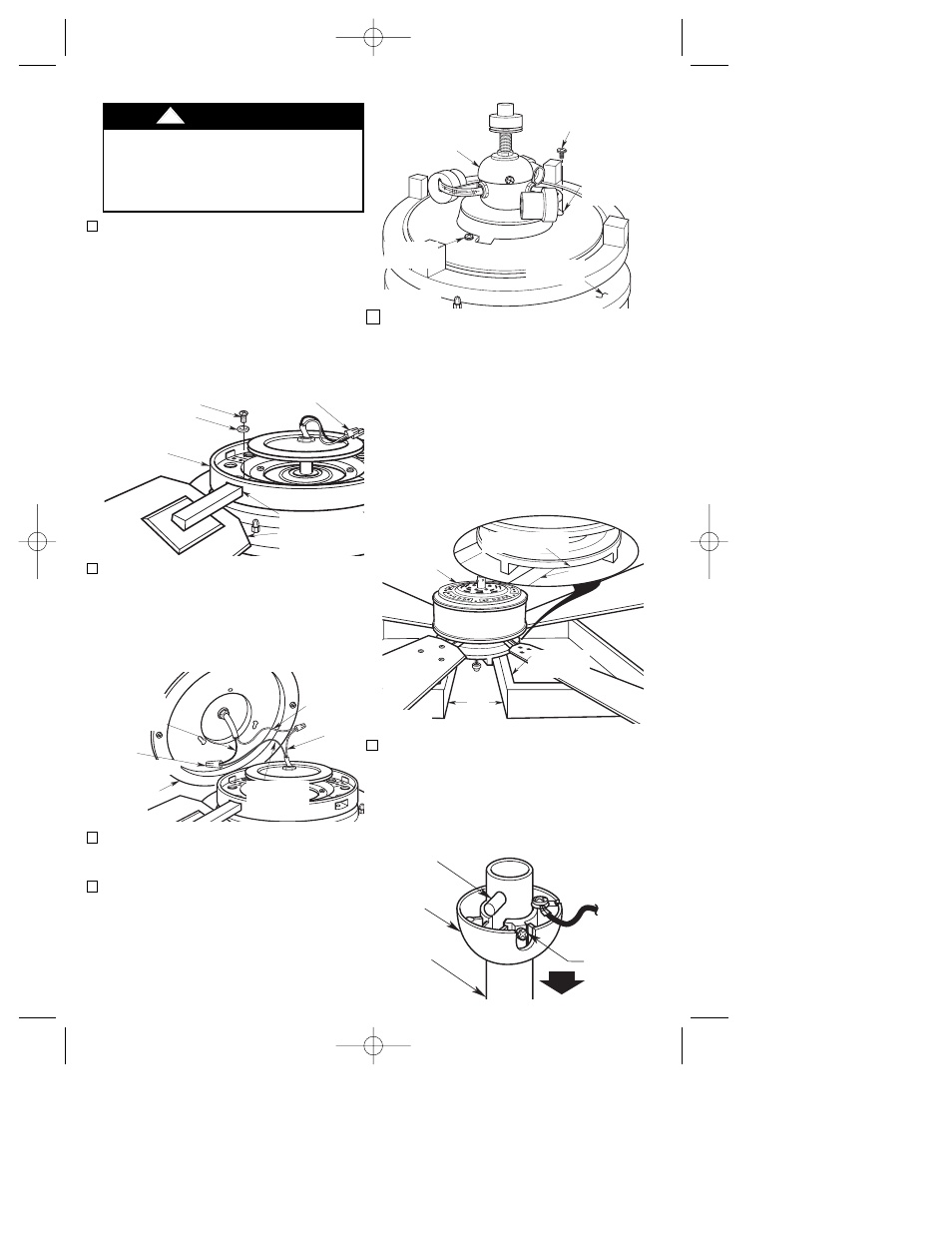
7. Remove the hanger ball by loosening
the setscrew in the hanger ball until the
ball falls freely down the 8” downrod
(Figure 6). Remove the clevis pin from
the downrod, then remove the hanger
ball. Retain the pin and hanger ball for
reinstallation in Step 13.
PIN
HANGER
BALL
SETSCREW
8" DOWNROD
Figure 6
6
LIGHT KIT
ASSEMBLY
WIRE
CONNECTOR (2)
LIGHT KIT
ASSEMBLY
BLACK WIRE
LIGHT KIT
ASSEMBLY
WHITE WIRE
MOTOR
WHITE
WIRE
MOTOR BLUE
WIRE
Figure 3
BP7333 CF750 MAYA ZEN 12/22/06 7:59 AM Page 6