Reguserdestid[3, Reguserdestid[2, Reguserdestid[1 – Linx Technologies TRM-915-R250 User Manual
Page 27: Reguserdestid[0, Regusersrcid[3, Regusersrcid[2, Regusersrcid[1, Regusersrcid[0, Reguseridmask[3, Reguseridmask[2
– –
– –
48
49
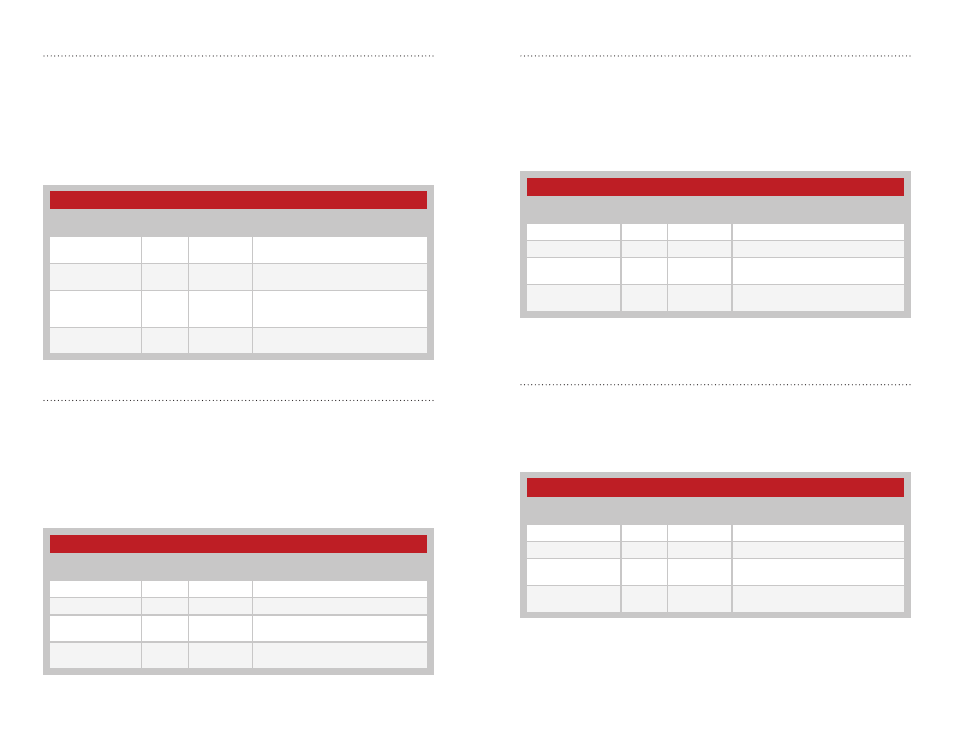
User ID Mask
These registers contain the user ID mask when User Networking mode
or Extended User Networking mode are enabled. User Networking mode
uses bytes 0 and 1 and Extended User Networking mode uses all four
bytes. Please see the Networking Modes section for more details. Each
register byte is read and written separately.
Figure 53 shows the User ID Mask Registers.
Destination GUID
These registers contain the address of the destination module when GUID
Networking Mode is enabled. Please see the Networking Modes section for
more details. Each register byte is read and written separately.
Figure 54 shows the Destination ID Registers.
250 Series User ID Mask Registers
Name
Volatile
Address
Non-Volatile
Address
Description
regUSERIDMASK[3]
0x62
0x17
MSB of the extended mask
regUSERIDMASK[2]
0x63
0x18
Byte 2 of the extended mask
regUSERIDMASK[1]
0x64
0x19
Byte 1 of the extended mask
MSB of the short mask
regUSERIDMASK[0]
0x65
0x1A
LSB of the extended mask and short
mask
Figure 53: 250 Series User ID Mask Registers
250 Series Destination GUID Registers
Name
Volatile
Address
Non-Volatile
Address
Description
regDESTGUID[3]
0x68
0x1D
MSB of the destination GUID
regDESTGUID[2]
0x69
0x1E
Byte 2 of the destination GUID
regDESTGUID[1]
0x6A
0x1F
Byte 1 of the destination GUID
MSB of the short destination GUID
regDESTGUID[0]
0x6B
0x20
LSB of the extended and short
destination GUID
Figure 54: 250 Series Destination GUID Registers
User Destination ID
These registers contain the address of the destination module when
User Networking mode or Extended User Networking mode are enabled.
User Networking mode uses bytes 0 and 1 to determine the destination
address. Extended User Networking mode uses all four bytes. Please see
the Networking Modes section for more details. Each register byte is read
and written separately.
Figure 51 shows the User Destination ID Registers.
User Source ID
These registers contain the address of the source module when User
Networking mode or Extended User Networking mode are enabled. User
Networking mode uses bytes 0 and 1 to determine the source address.
Extended User Networking mode uses all four bytes. Please see the
Networking Modes section for more details. Each register byte is read and
written separately.
Figure 52 shows the User Source ID Registers.
250 Series User Destination ID Registers
Name
Volatile
Address
Non-Volatile
Address
Description
regUSERDESTID[3]
0x5A
0x0F
MSB of the extended destination
address
regUSERDESTID[2]
0x5B
0x10
Byte 2 of the extended destination
address
regUSERDESTID[1]
0x5C
0x11
Byte 1 of the extended destination
address, MSB of the short destination
address
regUSERDESTID[0]
0x5D
0x12
LSB of the extended destination
address and short destination address
Figure 51: 250 Series User Destination ID Registers
250 Series User Source ID Registers
Name
Volatile
Address
Non-Volatile
Address
Description
regUSERSRCID[3]
0x5E
0x13
MSB of the extended source address
regUSERSRCID[2]
0x5F
0x14
Byte 2 of the extended source address
regUSERSRCID[1]
0x60
0x15
Byte 1 of the extended source address
MSB of the short source address
regUSERSRCID[0]
0x61
0x16
LSB of the extended source address
and short source address
Figure 52: 250 Series User Source ID Registers