Regusecrc, Reguartmtu, Regnvusecrc – Linx Technologies TRM-915-R250 User Manual
Page 24: Regnvuartmtu
– –
– –
42
43
UART Minimum Transmission Unit - Addr = 0x54; NV Addr = 0x09
This register determines the UART buffer level that triggers the transmission
of a packet. The minimum value is decimal 1 and the maximum value
is 192. The default value for this register is 64, which provides a good
mix of throughput and latency. At the maximum data rate, a value of
128 optimizes throughput. This register does not guarantee a particular
transmission unit size; rather, it specifies the minimum desired size. If there
is not enough time left in a hop, for instance, the protocol engine sends as
many characters as it can to fill the current hop, and sends the remaining
characters in the next hop. Figure 42 shows examples of the commands.
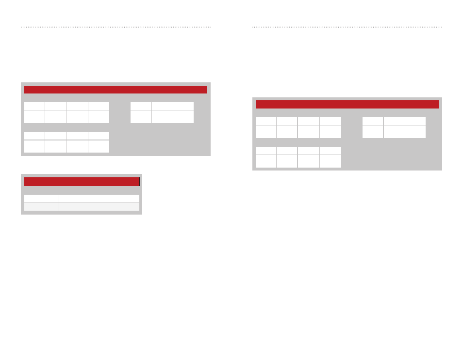
Figure 42: 250 Series UART MTU Command and Response
250 Series UART MTU
Read Command
Read Response
Header
Size
Escape
Address
ACK
Address
Value
0xFF
0x02
0xFE
0x54
0x09
0x06
0x54
0x09
V1
Write Command
Header
Size
Address
Value
0xFF
0x02
0x54
0x09
V1
CRC Control - Address = 0x53; NV Address = 0x08
The 250 Series protocol includes a Cyclic Redundancy Check on the
received packets to make sure that there are no errors. Any packets
with errors are discarded and not output on the UART. This feature can
be disabled if it is desired to perform error checking outside the module.
Set the regUSECRC register to 0x01 to enable CRC checking, or 0x00
to disable it. The default CRC mode setting is enabled. Figure 40 shows
examples of the commands and Figure 41 shows the available values.
250 Series CRC Control Register Settings
V1
Mode
0x00
CRC Disabled
0x01
CRC Enabled
Figure 40: 250 Series CRC Control Command and Response
Figure 41: 250 Series CRC Control Register Settings
250 Series CRC Control
Read Command
Read Response
Header
Size
Escape
Address
ACK
Address
Value
0xFF
0x02
0xFE
0x53
0x08
0x06
0x53
0x08
V1
Write Command
Header
Size
Address
Value
0xFF
0x02
0x53
0x08
V1