Reguartdatarate, Regnetworkmode, Regnvuartdatarate – Linx Technologies TRM-915-R250 User Manual
Page 22: Regnvnetworkmode
– –
– –
38
39
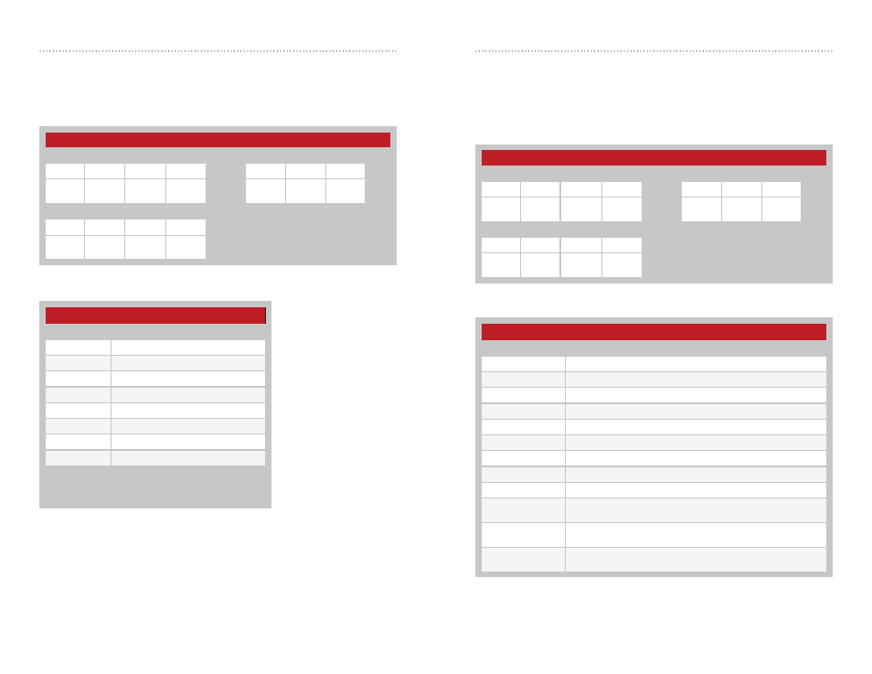
Network Mode - Address = 0x4F; NV Address = 0x04
The module supports three networking modes: GUID, User, and Extended
User. For each of these modes, assured delivery (acknowledgement) and
extended preamble can be either enabled or disabled.
Figure 34 shows the command and response and Figure 35 shows the
valid settings.
Figure 35: 250 Series Network Mode Register Settings
250 Series Network Mode Register Settings
Network Mode
Meaning
0x04
GUID Networking Mode
0x06
User Networking Mode
0x07
Extended User Networking Mode
0x0C
GUID Networking Mode with Extended Preamble
0x0E
User Networking Mode with Extended Preamble
0x0F
Extended User Network Mode with Extended Preamble
0x14
GUID Networking Mode with Acknowledgement
0x16
User Networking Mode with Acknowledgement
0x17
Extended User Networking Mode with Acknowledgement
0x1C
GUID Networking Mode with Acknowledgement & Extended
Preamble
0x1E
User Networking Mode with Acknowledgement & Extended
Preamble
0x1F
Extended User Networking Mode with Acknowledgement &
Extended Preamble
Figure 34: 250 Series Network Mode Command and Response
250 Series Network Mode
Read Command
Read Response
Header
Size
Escape
Address
ACK
Address
Value
0xFF
0x02
0xFE
0x4F
0x04
0x06
0x4F
0x04
V1
Write Command
Header
Size
Address
Value
0xFF
0x02
0x4F
0x04
V1
UART Data Rate - Address = 0x4E; NV Address = 0x03
The value in regUARTDATARATE sets the data rate of the UART interface.
Changing the non-volatile register changes the data rate on the following
power-up or reset. Changing the volatile register changes the data rate
immediately following the command acknowledgement. Figure 32 shows
the command and response and Figure 33 shows the valid settings.
If the UART rate is different than the host processor UART rate then the
module will not communicate correctly. If mismatched, every rate can be
tested until the correct one is found or the module can be reset to factory
defaults.
Figure 32: 250 Series UART Data Rate Command and Response
Figure 33: 250 Series UART Data Rate Settings
250 Series UART Data Rate Register Settings
V1
Baud Rate
0x00
2,400
0x01
9,600
0x02
19,200
0x03
38,400
0x04
57,600
0x05
115,200
0x06
10,400*
0x07
31,250*
* These data rates are not supported by PC serial ports.
Selection of these rates may cause the module to fail to
respond to a PC, requiring a reset to factory defaults.
250 Series UART Data Rate
Read Command
Read Response
Header
Size
Escape
Address
ACK
Address
Value
0xFF
0x02
0xFE
0x4E
0x03
0x06
0x4E
0x03
V1
Write Command
Header
Size
Address
Value
0xFF
0x02
0x4E
0x03
V1