Module configuration – Linx Technologies TRM-915-R250 User Manual
Page 18
– –
– –
30
31
Module Configuration
The 250 Series module contains several registers that control its
configuration and operation. The module’s default settings allow it to
operate out of the box without any changes; however the registers allow
the link to be customized to better suit the application if necessary. The
register settings are stored in two types of memory inside the module.
Volatile memory is quick to access, but it is lost when power is removed
from the module. Non-volatile memory takes longer to access, but is
retained when power is removed.
All of the configuration settings have registers in both types of memory.
The settings are read from non-volatile registers on power up and saved in
volatile registers. The values in the volatile registers are used during normal
operation since it is faster to read and write the volatile memory locations.
There are commands to read and write both locations.
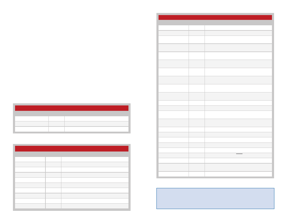
Figure 21 shows the volatile read-only registers. Figure 22 shows the
volatile read and write registers. Figure 23 shows the non-volatile read-only
registers. Figure 24 shows the non-volatile read and write registers.
Figure 21: 250 Series Volatile Read Only Configuration Registers
Figure 22: 250 Series Volatile Read / Write Configuration Registers
250 Series Volatile Read / Write Configuration Registers
Name
Address
Description
0x40
CRC error count value
0x4B
Hop table
0x4D
Power amplifier setting
0x4E
UART data rate
0x4F
Sets the networking mode
0x50
UART to transmit timeout
0x52
Maximum times to retry packet transmission
0x53
Enable / Disable CRC checking
0x54
Minimum transmission unit
0x56
Enable / Disable CSMA
250 Series Volatile Read-Only Configuration Registers
Name
Address
Description
0x79
Stores latest exception code
0x7B
Last Good Packet RSSI value
0x7C
Current RSSI value
250 Series Volatile Read / Write Configuration Registers Continued
Name
Address
Description
0x58
Sets operating mode
0x59
Enable / Disable ACK sent to UART upon wake
0x5A
Destination Address for Extended User Networking
Mode
0x5B
Destination Address for Extended User Networking
Mode
0x5C
Destination Address for User and Extended User
Networking Mode
0x5D
Destination Address for User and Extended User
Networking Mode
0x5E
Source Address for Extended User Networking
Mode
0x5F
Source Address for Extended User Networking
Mode
0x60
Source Address for User and Extended User
Networking Mode
0x61
Source Address for User and Extended User
Networking Mode
0x62
Address Mask for Extended User Networking Mode
0x63
Address Mask for Extended User Networking Mode
0x64
Address Mask for User and Extended User
Networking Mode
0x65
Address Mask for User and Extended User
Networking Mode
0x68
GUID Networking Mode Destination Address
0x69
GUID Networking Mode Destination Address
0x6A
GUID Networking Mode Destination Address
0x6B
GUID Networking Mode Destination Address
0x6C
Exception and Mask used to activate the EX line
0x6E
Half RF traffic when the CMD line is low
0x6F
Receiver LNA gain / linearity setting
0x70
Compatibility mode for 25 and 250
intercommunication
0x71
Sets automatic addressing
Warning:
Modules that are not configured in the same way will not be
able to communicate reliably, causing poor performance or outright
failure of the wireless link. All modules in a network must have compatible
configurations to ensure interoperability.