Regpwrmode, Regnvpwrmode – Linx Technologies TRM-915-R250 User Manual
Page 21
– –
– –
36
37
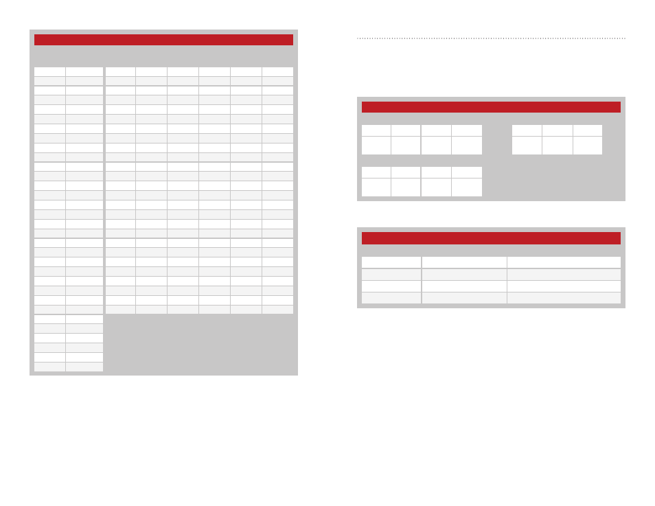
Power Mode - Address = 0x4D; NV Address = 0x02
The value in the regPWRMODE register sets the module’s output power.
Figure 30 shows the command and response and Figure 31 available
power settings and typical power outputs for the module. The default
setting is 0x03.
250 Series Power Mode Register Settings
PWR
Power Setting
Typical Output Power (dBm)
0x00
Low
+8
0x01
Mid – Low
+13
0x02
Mid – High
+18
0x03
High
+23.5
Figure 30: 250 Series Power Mode Command and Response
Figure 31: 250 Series Power Mode Settings
250 Series Power Mode
Read Command
Read Response
Header
Size
Escape
Address
ACK
Address
Value
0xFF
0x02
0xFE
0x4D
0x02
0x06
0x4D
0x02
PWR
Write Command
Header
Size
Address
Value
0xFF
0x02
0x4D
0x02
PWR
250 Series RF Channels and Hop Sequences
Channel
Number
Frequency
(MHz)
Hop Sequence by Channel Number
0
1
2
3
4
5
0
902.971
16
15
3
28
22
9
1
903.723
1
30
20
11
7
24
2
904.475
2
29
21
10
8
23
3
905.226
5
26
24
7
11
20
4
905.978
10
21
29
2
16
15
5
906.730
21
10
8
23
27
4
6
907.482
11
20
30
1
17
14
7
908.234
23
8
10
21
29
2
8
908.986
14
17
1
30
20
11
9
909.737
29
2
16
15
3
28
10
910.489
27
4
14
17
1
30
11
911.241
22
9
9
22
28
3
12
911.993
12
19
31
0
18
13
13
912.745
24
7
11
20
30
1
14
913.496
17
14
4
27
23
8
15
914.248
3
28
22
9
9
22
16
915.000
7
24
26
5
13
18
17
915.752
15
16
2
29
21
10
18
916.504
31
0
18
13
5
26
19
917.255
30
1
17
14
4
27
20
918.007
28
3
15
16
2
29
21
918.759
25
6
12
19
31
0
22
919.511
19
12
6
25
25
6
23
920.263
6
25
25
6
12
19
24
921.015
13
18
0
31
19
12
25
921.766
26
5
13
18
0
31
26
922.518
27
923.270
28
924.022
29
924.774
30
925.525
31
926.277
Figure 29: 250 Series RF Channels and Hop Sequences