Chapter 2, System components, Rear components – Lanner LEC-7110 User Manual
Page 9
9
System Components
Chapter 2
Embedded and Industrial Computing
Rear Components
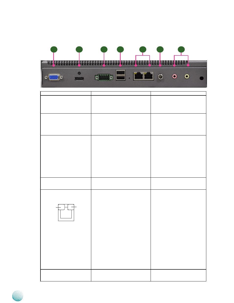
Component
Description
Pin Definition Reference
R1 VGA Port
DB-15 Female Connector for VGA
connection (up to 1920x1200).The
graphic engine is provided by Intel
onboard graphic GMA3150.
VGA1 on page 16
R2 HDMI
An HDMI port which also
integrates with an audio output
offers maximum resolution up to
1920x1200. The graphic engine is
provided by Intel GMA 3150.
HDMI1 Connector on page 16
R3 DIO Port
4 digital input and 4 output ports
to support input and output
operations. The MCU and its flash
will help to retain the DIO last state
even when the system reboots
or shuts down. Refer to Chapter
3 Board Layout and Appendix
B Digital Input/Output for DIO
control.
DI1 on page 15
R4 Dual USB Stack Connector An USB type A connector; in
addition to this connector, an
internal pin header is provided.
USB1 on Page 15
R5 Dual 10/100/1000 LAN
Ports
Two RJ-45 (network) jacks with LED
indicators as described below. The
LAN ports are provided by Realtek
RTL8111. They both support WOL
(Wake-on-LAN) and Remote-wake-
up.
LINK/ACT (Yellow)
On/Flashing: The port is linking
•
and active in data transmission.
Off: The port is not linking.
•
SPEED (Green/Amber)
Amber: The connection speed is
•
1000Mbps.
Green: The connection speed is
•
100Mbps
Off: .The connection speed is
•
10Mbps.
LAN1_1/1_2 on page 13
R6 DC Jack
DC-in 12V power socket with
Lock. Only use the power adapter
supplied with the LEC-7110 System.
DC_IN1 on page 16
R1
R2
R3
R4
R5
R6
SPEED
LINK/ACT
R7