Appendix c, Appendix c: digital input/output, Digital input/output control – Lanner LEC-7110 User Manual
Page 24
24
Digital Input/Output Control
Appendix C
Embedded and Industrial Computing
Appendix C:
Digital Input/Output
The Digitanl I/O on the rear panel is designed to provide
the input and output operation for the system. For sample
DIO code, see DIO folder under LEC-7110 Utility in the
Driver and Manual CD.
Install IOA3_Demo Program on Windows
Refer to Appendix A: Lanner GPIO driver installation to
install Lanner GPIO driver first and then Install IOA3_
DemoSetup.msi
Via the Command Line
Specific to the PCH chipset used or Super IO chipset, the
commands and functionality vary by product models.
For more information, refer to the README or User Guide
contained within the utility folder.
For example: Here we have IOA3 utility, to execute, follow
the command description below:
The IOA3 utility for Digital Input/
Output-------------------------------------
The IOA3 device utility (ioa3.exe) Usage:
IOA3 COM3 GET VariableName
IOA3 COM3 SET VariableName value
IOA3 COM3 “get output_state” (get the high/low state for
the digital_OUT ports)
“set output_state decimal value of the port” (set
the high/low state for digital_OUT ports)
“get input_state” (get the high/low state for the
digital_IN ports)
Argument:
The decimal value of port is calculated as shown in the
following table:
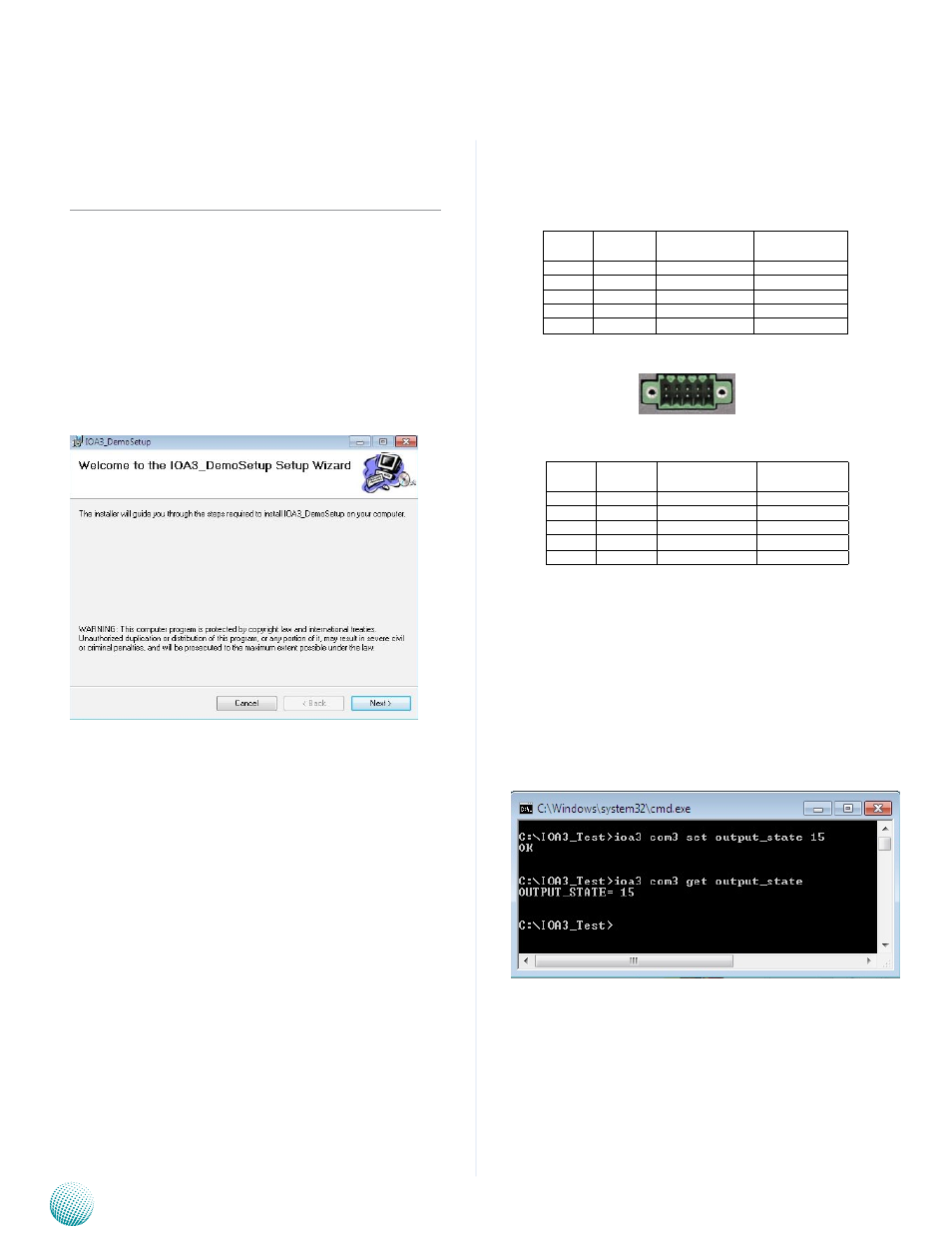
For instance, to set the output state to DO3, DO2, DO1,
DO0=1 1 1 1, type:
IOA3 COM3 set output_state 15
Likewise, to get the output state of DO3, DO2, DO1, DO0:
IOA3 COM3 get output_state
Pin No. Pin Name
binary
representation
decimal
representation
1
Input0
1000
8
3
Input1
0100
4
5
Input2
0010
2
7
Input3
0001
1
9
GND
Pin No. Pin Name
binary
representation
decimal
representation
2
Output0
1000
8
4
Output1
0100
4
6
Output2
0010
2
8
Output3
0001
1
10
GND
1 3 5 7 9
2 4 6 8 10