Chapter 2, System components, Front components – Lanner LEC-7110 User Manual
Page 8
8
System Components
Chapter 2
Embedded and Industrial Computing
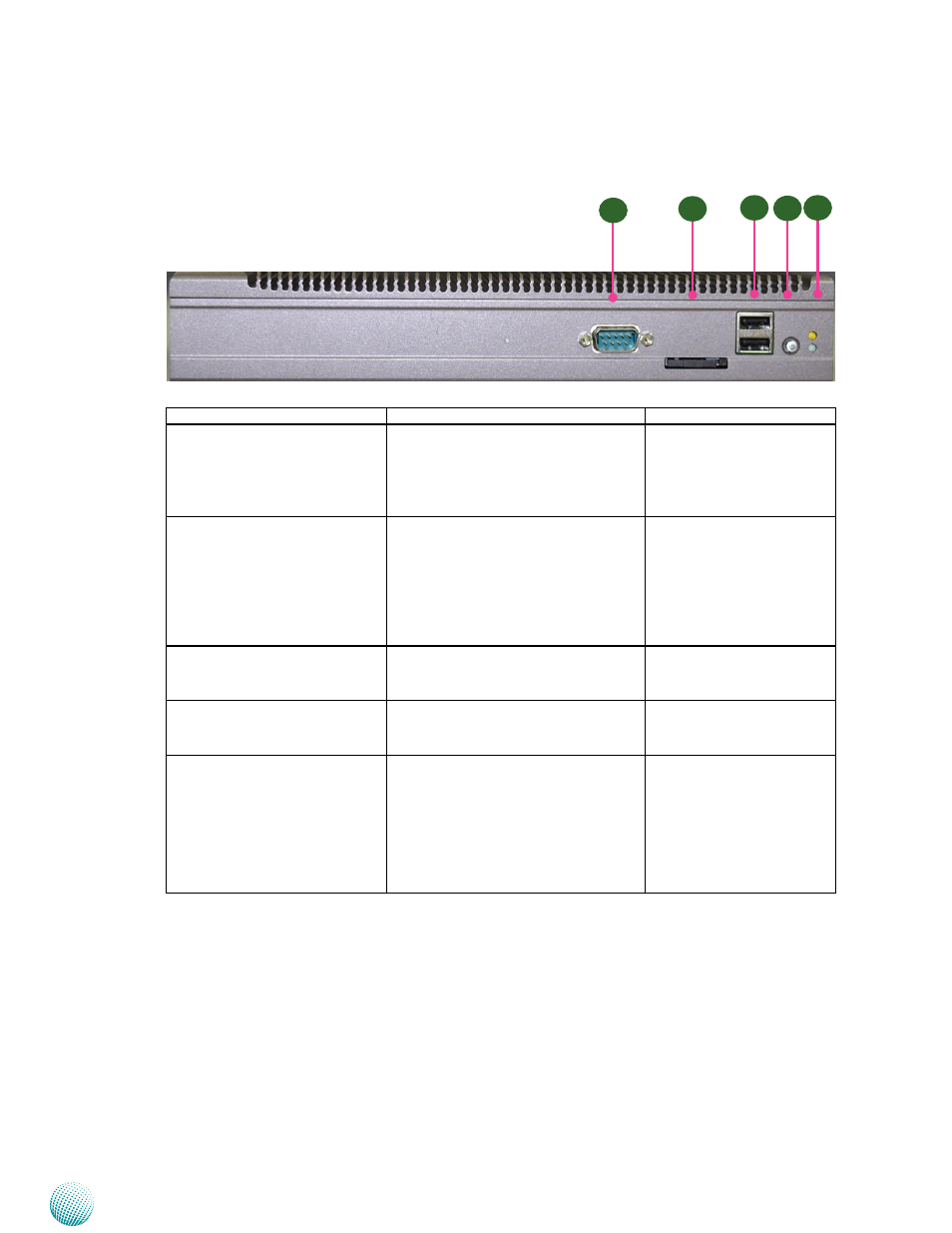
Front Components
Component
Description
Pin Definition Reference
F1 COM Port 1
Serial ports through the DB-9
connector; COM1 supports RS-232
communication protocol. In addition to
this port, a pin header is also provided
(COM2 in RS-232)
JCOMA1 on page 14
F2 SIM Card Reader
External SIM card reader for wireless 3G
connection. To open the reader, Insert
the tip of a pointy object (or a small
paper clip) into the SIM eject lever on
the SIM card reader. Press firmly and
push it straight in until the tray pops
out.
F3 Dual USB Stack Connector
An USB type A connector; in addition to
this connector, an internal pin header is
provided.
USB3 on page 15
F4 Power Button with dual LED ATX Power-on button with LEDs:
Standby mode in Red; Power-on mode
in Green
F5 HDD (Yellow) and
Power LED (Green)
HDD
Blinking: data access activities
•
Off: no data access activities
•
Power
On: The computer is on.
•
Off: The computer is off .
•
F2
F1
F3
F4
F5