Jordan Valve Mark V-100 Series Control Valve User Manual
Page 2
M
ark
V-100 S
erieS
C
ontrol
V
alVeS
-2-
M
aIntenance
Scheduled inspections and maintenance are vital to
continued operation of all pressure control valves and
systems. Parts are subject to wear and tear and must
be replaced as necessary, depending on the intensity of
service conditions.
Warning:
To avoid personal injury or damage to the process
system, disconnect operating lines providing air
pressure, control signals or electrical power to the
actuator. Ensure the actuator cannot suddenly open
or close.
Isolate the valve from the system by using by-pass
valves or by shutting off the process entirely. Relieve
any pressure contained on both sides of the valve
and drain the process media.
Vent the power actuator, relieve actuator spring pres-
sure and use proper lock-out methods during all
maintenance procedures.
Replacing Packing
When conducting packing maintenance, the actuator
must be removed from the valve. It is also recommend-
ed that the valve be removed from the pipeline to allow
for adjustment of the valve closed position.
If the packing is new and tight on the shaft, and if leak-
age cannot be stopped by tightening the packing nuts, it
is likely that the shaft has become worn or nicked.
If the leakage originates from the outside diameter of
the packing, nicks or scratches may have damaged the
packing box wall. Inspect the shaft and packing box
during the following procedures.
If it is not possible to control leakage around the valve
shaft by tightening packing flange bolts, the packing
may need to be replaced.
Split Ring Packing
Before beginning any maintenance, it is important to iso-
late the control valve and release all pressure contained
in the valve body and the actuator.
Note: exercise caution during disassembly. Nicks
and scratches will affect the ability to seal the valve
in the future.
1.
Remove packing flange nuts (key 3) and lift the
packing follower (key 15) from the packing box.
2.
With a formed wire hook remove the packing
rings.
3.
Clean the packing box, all metal parts, and co-
mplete the required maintenance.
4.
Expand the split ring of the new packing to allow
it to pass over the valve shaft. Stager the con-
necting lines, then slide the rings into the pack-
ing box.
5.
Tighten the packing flange nuts until they are fin-
ger tight. Test under flow conditions. Continue
tightening the nuts until all leakage has stopped.
Solid Ring Packing
Isolate the control valve. Release all pressure contained
in the valve body, and the actuator. Prior to disassembly,
note the orientation of the actuator and lever in relation
to the valve body.
Use caution when removing the actuator lever, using
a wheel-puller if necessary. If the actuator lever is
forced off the valve shaft the ball could move from
the centered position, damaging the V-Ball, seal and
valve body.
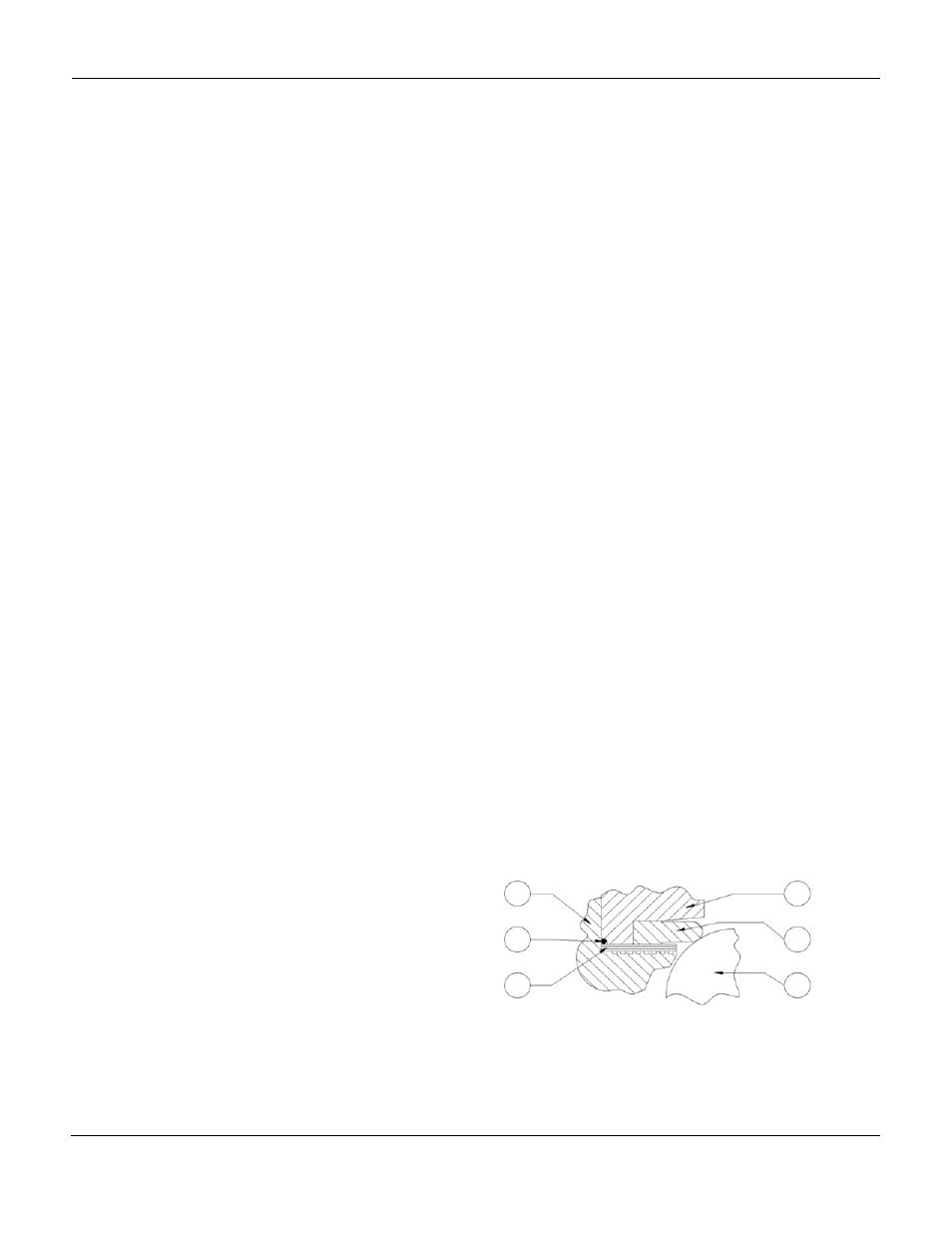
Figure 1. Section view of Heavy Duty
Composition (TCM) Ball Seal
7
24
20
21
23
22