Yaskawa SmartTrac Ethernet Card User Manual
Page 36
SMART TRAC Ethernet Card
34
••
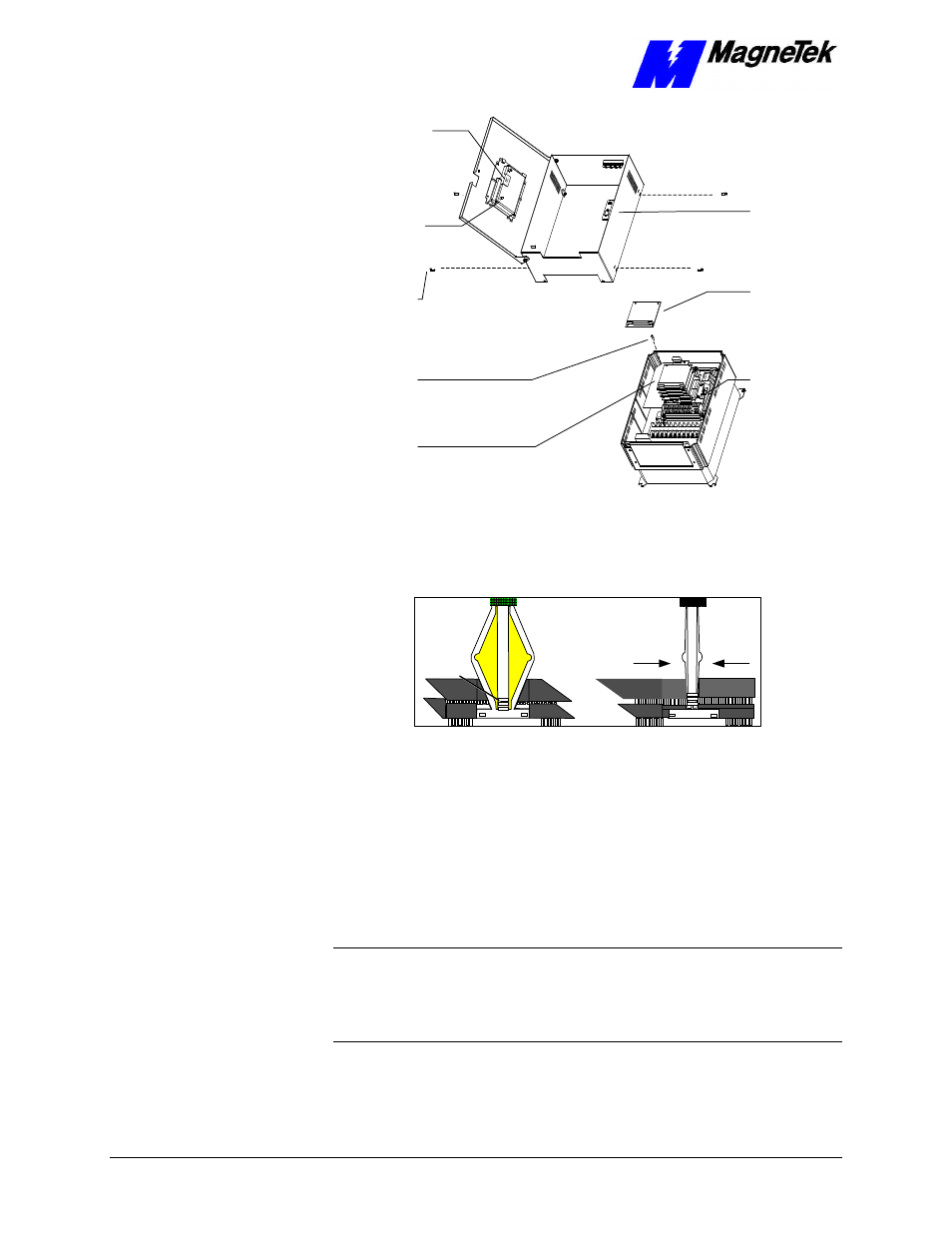
Appendix D – Removing the Smart Trac Card Stack Technical Manual Smart Trac Ethernet Card
12-pin wiring
harness on
Digital Operator
attached to
connector J4 on
Smart Trac
CPU Card
Digital
Operator
4mm screws
(4 places)
secure ring
to main
chassis
Standoffs (4
places)
secure each
board
Smart Trac
Board Stack
9-pin RS-232
cable
connector J5
PC/104
board
9-pin RS-232
cable
attached here
6. Using a 4.5mm hex head driver, remove four standoffs from the
topmost card.
7. Using the PC/104 extraction tool, remove the topmost card from the
stack.
Squeeze to lift
cards apart
Position
rectangular
"jacks"
around
edges of
PCBs
Figure 8. Using the PC/104 Extraction Tool.
8. Repeat step 8 above until all PC/104 cards have been removed.
9. To remove the Smart Trac PG card:
•
Disconnect the 4CN connector on the PG card.
•
Using a tubular extraction tool or pliers, squeeze the plastic,
spring-loaded retainer built-in to the long plastic standoff located
at the top of the PG card, just above connector J6.
•
Using a PC/104 extraction tool, remove the card.
NOTE: The Smart Trac PG card requires unique handling. Wedge the extracting
tool between the PG card and the CPU card. The area between the terminal strip
on the CPU card and the serial numbered edge of the PG card can be lifted first,
then the opposite side (nearest TB1) on the PG card). Alternate sides until the
card is free of the CPU card.
10. To remove the Smart Trac CPU card: