Yaskawa AC Drive-L1000E Safety Precautions User Manual
Page 44
9 Standards Compliance
44
YASKAWA TOEP YAIL1E 02A YASKAWA AC Drive - L1000E Safety Precautions
Low Voltage Wiring for Control Circuit Terminals
Wire low voltage wires with NEC Class 1 circuit conductors. Refer to national state or local codes for wiring. If external
power supply used, it shall be UL Listed Class 2 power source only or equivalent. Refer to NEC Article 725 Class 1,
Class 2, and Class 3 Remote-Control, Signaling, and Power Limited Circuits for requirements concerning class 1 circuit
conductors and class 2 power supplies.
Table 18 Control Circuit Terminal Power Supply
Drive Motor Overload Protection
Set parameter E2-01/E5-03 (motor rated current) to the appropriate value to enable motor overload protection. The
internal motor overload protection is UL listed and in accordance with the NEC and CEC.
E2-01/E5-03: Motor Rated Current (IM Motor/PM Motor)
Default Setting and Range: Model Dependent
Parameter E2-01/E5-03 (motor rated current) protects the motor if parameter L1-01 is not set to 0 (default is 1, enabling
protection for standard induction motors).
If Auto-Tuning has been performed successfully, the motor data entered to T1-04/T2-04 is automatically written into
parameter E2-01/E5-03. If Auto-Tuning has not been performed, manually enter the correct motor rated current to
parameter E2-01/E5-03.
L1-01: Motor Overload Protection Selection
The drive has an electronic overload protection function (oL1) based on time, output current, and output speed, which
protects the motor from overheating. The electronic thermal overload function is UL-recognized, so it does not require an
external thermal relay for single motor operation.
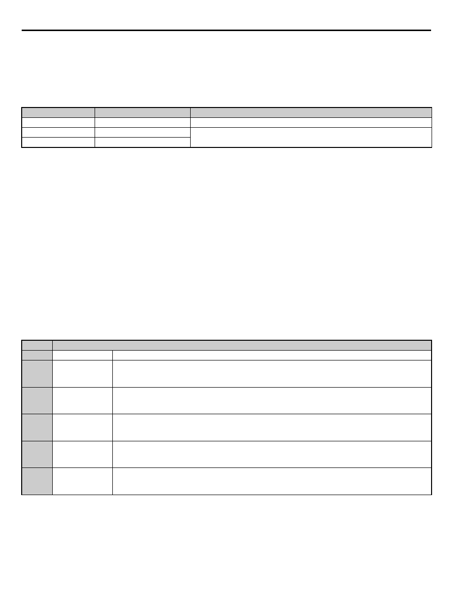
Table 19 L1-01 Motor Overload Protection Settings
When connecting the drive to more than one motor for simultaneous operation, disable the electronic overload protection
(L1-01 = 0) and wire each motor with its own motor thermal overload relay.
Enable the motor overload protection (L1-01 = 1 to 3, 5) when connecting the drive to a single motor, unless another
motor overload preventing device is installed. The drive electronic thermal overload function causes an oL1 fault, which
shuts off the output of the drive and prevents additional overheating of the motor. The motor temperature is continually
calculated while the drive is powered up.
Input / Output
Terminal Signal
Power Supply Specifications
Open Collector Outputs
P1, C1, P2, C2, DM+, DM-
Requires class 2 power supply
Digital inputs
S1-S8, SN, SC, SP, HC, H1, H2 Use the internal LVLC power supply of the drive. Use class 2 for external power
supply.
Analog inputs / outputs
+V, -V, A1, A2, AC, AM, FM
Setting
Description
0
Disabled
Disabled the internal motor overload protection of the drive.
1
Standard fan-cooled
motor (default)
Selects protection characteristics for a standard self cooled motor with limited cooling capabilities when running
below the rated speed. The motor overload detection level (oL1) is automatically reduced when running below the
motor rated speed.
2
Drive duty motor
with a speed range
of 1:10
Selects protection characteristics for a motor with self-cooling capability within a speed range of 10:1. The motor
overload detection level (oL1) is automatically reduced when running below 1/10 of the motor rated speed.
3
Vector motor with a
speed range of
1:100
Selects protection characteristics for a motor capable of cooling itself at any speed — including zero speed
(externally cooled motor). The motor overload detection level (oL1) is constant over the entire speed range.
5
Permanent Magnet
motor with constant
torque
Selects protection characteristics for a constant torque PM motor. The motor overload detection level (oL1) is
constant over the whole speed range.
6
Standard fan cooled
motor (50 Hz)
Selects protection characteristics for a standard self cooled motor with limited cooling capabilities when running
below the rated speed. The motor overload detection level (oL1) is automatically reduces when running below the
motor rated speed.