Installation orientation and spacing, Instructions on installation, Installation orientation – Yaskawa AC Drive-L1000E Safety Precautions User Manual
Page 10: Installation spacing
4 Mechanical Installation
10
YASKAWA TOEP YAIL1E 02A YASKAWA AC Drive - L1000E Safety Precautions
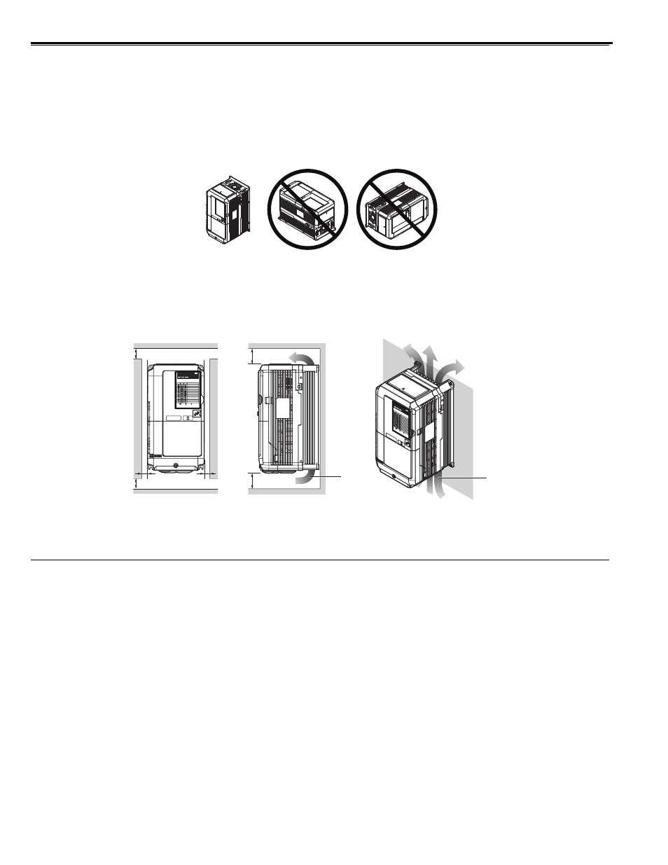
Installation Orientation and Spacing
WARNING! Fire Hazard. Provide sufficient cooling when installing the drive inside an enclosed panel or cabinet. Failure to comply
could result in overheating and fire. When drives are placed inside the same enclosure panel, install proper cooling to ensure air
entering the enclosure does not exceed 40
°C (104°F).
Installation Orientation
Install the drive upright as illustrated in
to maintain proper cooling.
Figure 1
Figure 1 Correct Installation Orientation
Installation Spacing
shows the installation distance required to maintain sufficient space for airflow and wiring.
Figure 2
Figure 2 Correct Installation Spacing
Instructions on Installation
Eye bolts are used to install the drive or to temporarily lift the drive when replacing it. The drive can be installed in an
enclosure panel or on a wall. Do not leave the drive suspended by the wires in a horizontal or vertical position for long
periods of time. Do not transport the drive over long distances. Read the following precautions and instructions before
installing the drives.
WARNING! Crush Hazard. Be sure to observe the following instructions and precautions. Failure to comply could result in minor or
moderate injury and damage to the drive from falling equipment.
• Before using wires to suspend the drive vertically and horizontally, make sure that the drive front cover,
terminal blocks and other drive components are securely fixed with screws.
• Do not subject the drive to vibration or impact greater than 1.96 m/s
2
(0.2 G) while it is suspended by the
wires.
• Do not overturn the drive while it is suspended by the wires.
• Do not leave the drive suspended by the wires for long periods of time.
• Only allow qualified personnel to operate a crane or hoist to transport the drive.
• Use a dedicated lifter when transporting the drive by a lifter.
• Only use vertical suspension to temporarily lift the drive during installation to an enclosure panel. Do not
use vertical suspension to transport the drive.
A – 50 mm (1.97 in.) minimum
C – 120 mm (4.72 in.) minimum
B – 30 mm (1.18 in.) minimum
D – Airflow direction
A
A
B
B
Side Clearance
Top/Bottom Clearance
C
C
D
D
PWR
LED MONITOR JVOP-184
RUN
DS1
DS2
RUN DS1 DS2
STATUS
READY
RUN
ALARM(RUN)
PGOH,LT
BB,HBB
EF,SE
Other Fault
OV,UV
OH,OL
OC,GF,SC,PGO
CPF,OFA,OFB,OFC
:LIGHT
:BLINK
:LIGHT OFF
PW
R
LED M
ONIT
OR JV
OP-18
4
RUN
DS1
DS2
RUN
DS1
DS2
STAT
US
READ
Y
RUN
ALARM
(RUN
)
PGOH
,LT
BB,H
BB
EF,SE
Othe
r Fau
lt
OV,U
V
OH,O
L
OC,G
F,SC,P
GO
CPF
,OFA
,OFB
,OFC
:LIGH
T
:BLIN
K
:LIGH
T O
FF