Control circuit connections, Terminal configuration, 5 electrical installation – Yaskawa AC Drive-L1000E Safety Precautions User Manual
Page 26
5 Electrical Installation
26
YASKAWA TOEP YAIL1E 02A YASKAWA AC Drive - L1000E Safety Precautions
Control Circuit Connections
Drive parameters determine which functions apply to the multi-function digital inputs (S3 to S8), multi-function digital
outputs (M1 to M6), multi-function photocoupler outputs (P1-C1, P2-C2), multi-function analog inputs (A1, A2), and
multi-function analog monitor output (FM, AM). The default setting is listed next to each terminal in
on page
.
WARNING! Sudden Movement Hazard. Always check the operation and wiring of control circuits after being wired. Operating a drive
with untested control circuits could result in death or serious injury.
WARNING! Sudden Movement Hazard. Verify all drive fast-stop wiring and additional emergency circuits before operating the drive.
Operating a drive with untested emergency circuits could result in death or serious injury.
WARNING! Sudden Movement Hazard. Confirm the drive I/O signals and external sequence before starting test run. Failure to comply
may result in death or serious injury.
Note: Do not solder the ends of wire connections to the drive. Soldered wiring connections can loosen over time. Improper wiring
practices could result in drive malfunction due to loose terminal connections.
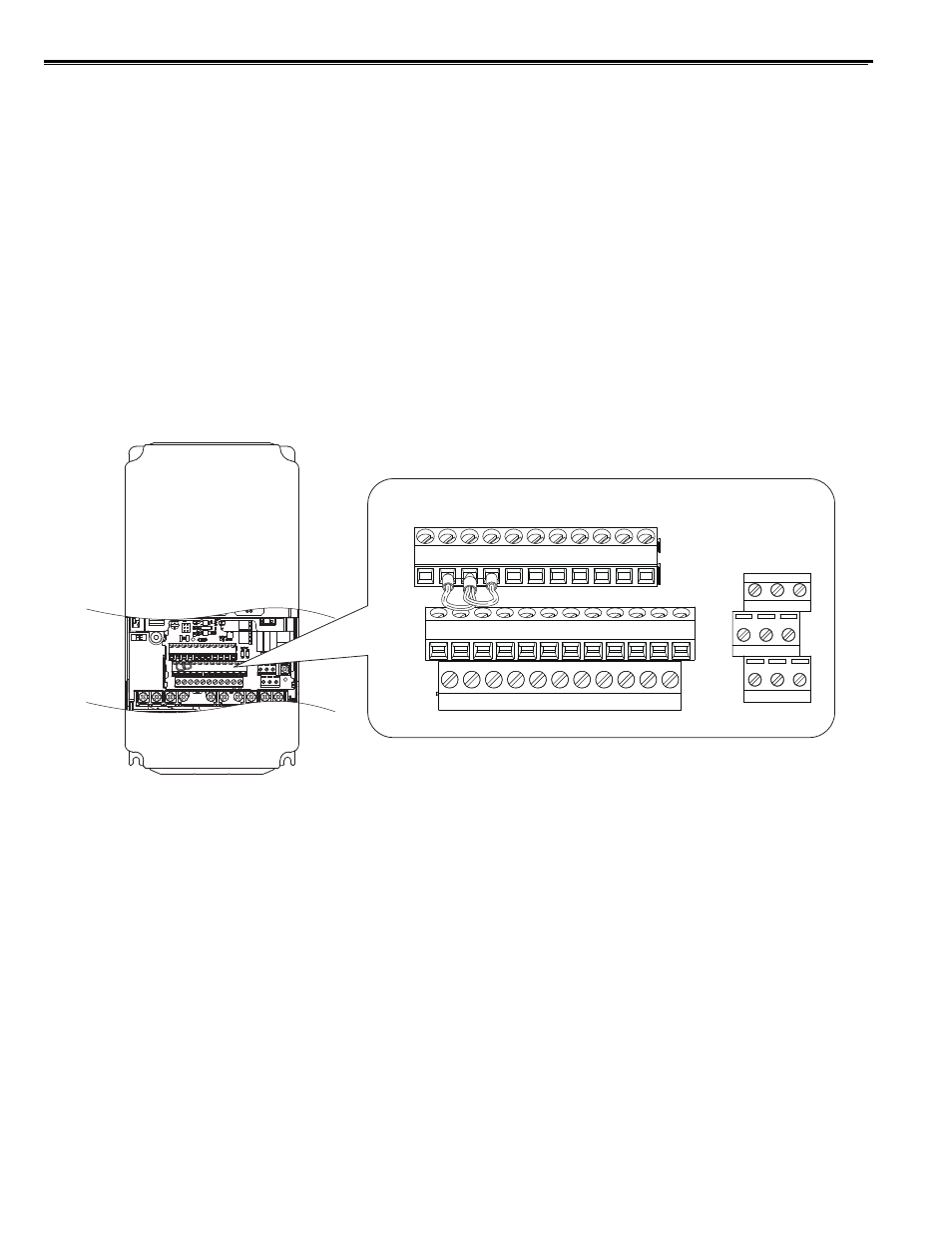
Terminal Configuration
Control circuit terminals are arranged as shown in
Figure 7
Figure 7 Control Circuit Terminal Arrangement
E(G) HC H1
H2 DM+ DM- IG
R+
R-
S+
S-
S1
S2
S3
S4
S5
S6
S7
S8
SN SC SP
V+ AC
V-
A1
A2 FM AM AC
P1
C1
C2
P2
M3 M4
M6
MA MB MC
M1 M2 M5