Control circuit input terminals – Yaskawa AC Drive-L1000E Safety Precautions User Manual
Page 27
5 Electrical Installation
YASKAWA TOEP YAIL1E 02A YASKAWA AC Drive - L1000E Safety Precautions
27
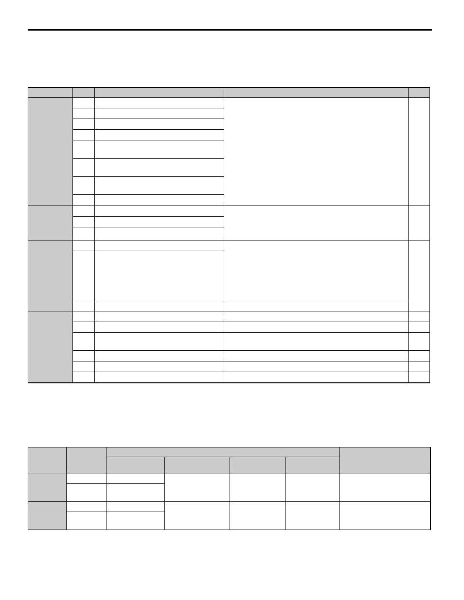
Control Circuit Input Terminals
lists the input terminals on the drive. Text in parenthesis indicates the default setting for each multi-function
input.
Table 8 Control Circuit Input Terminals
Terminals A1 and A2 can accept a voltage signal to supply the speed reference to the drive.
shows the parameter
settings and voltage levels required for each terminal.
Table 9 Analog Input Settings for Speed Reference Using Voltage Signals
Type
<1> Setting jumper S3 for an external power supply makes the wire jumper between terminals H1, H2, and HC ineffective. Remove the wire jumper
and connect an external power supply that can supply terminals H1, H2, and HC continuously.
No.
Terminal Name (Function)
Function (Signal Level) Default Setting
Page
Digital Inputs
S1
Up Command (Closed: Up, Open: Stop)
Photocoupler
24 Vdc, 8 mA
Use the wire link between terminals SC and SN or between SC
and SP to select sinking or sourcing, and to select the power
supply.
178
S2
Down Command (Closed: Down, Open: Stop)
S3
Multi-function input 1 (External Fault)
S4
Multi-function input 2 (Fault Reset)
S5
Multi-function input 3 (Multi-Step Speed
Reference 1)
S6
Multi-function input 4 (Multi-Step Speed
Reference 2)
S7
Multi-function input 5 (Multi-Step Speed
Reference 3)
S8
Multi-function input 6 (Not used)
Digital Input
Power Supply
SC
Multi-function input common
24 Vdc, 150 mA (only when DI-A3 is not used)
Use the wire jumper between terminals SC and SN or between SC
and SP to select sinking or sourcing, and to select the power
supply.
SN
0 V
SP
+24 Vdc
Safe Disable
Inputs
H1
Safe Disable input 1
24 Vdc, 8 mA
One or both open: Drive output disabled
Both closed: Normal operation
Internal impedance: 3.3 k
Ω
Off time of at least 1 ms
Set the S3 jumper to select sinking or sourcing, and to select the
power supply.
225
H2
Safe Disable input 2
HC
Safe Disable function common
Common for the Safe Disable function
Analog Inputs
+V
Power supply for analog inputs
10.5 Vdc (max allowable current 20 mA)
223
-V
Power supply for analog inputs
-10.5 Vdc (max allowable current 20 mA)
–
A1
Multi-function analog input 1 (Speed
reference bias)
-10 to 10 Vdc, 0 to 10 Vdc (input impedance: 20 k
Ω)
–
A2
Multi-function analog input 2 (Not used)
-10 to 10 Vdc, 0 to 10 Vdc (input impedance: 20 k
Ω)
–
AC
Analog input common
0 V
–
E (G) Ground for shielded lines and option cards
–
–
Terminal
Signal
Level
Parameter Settings
Notes
Signal Level
Selection
Function Selection
Gain
Bias
A1
0 to 10 Vdc
H3-01 = 0
H3-02 = 0
(speed reference bias)
H3-03
H3-04
–
-10 to +10
Vdc
H3-01 = 1
A2
0 to 10 Vdc
H3-09 = 0
H3-10 = 0
(speed reference bias)
H3-11
H3-12
–
-10 to +10
Vdc
H3-09 = 1