Profibus-dp data and i/o map – Yaskawa VS-616G5 Profibus-DP Control Card SI-P User Manual
Page 9
VS-616G5 Option Instruction Manual: Profibus-DP Control Card SI-P
Page 9
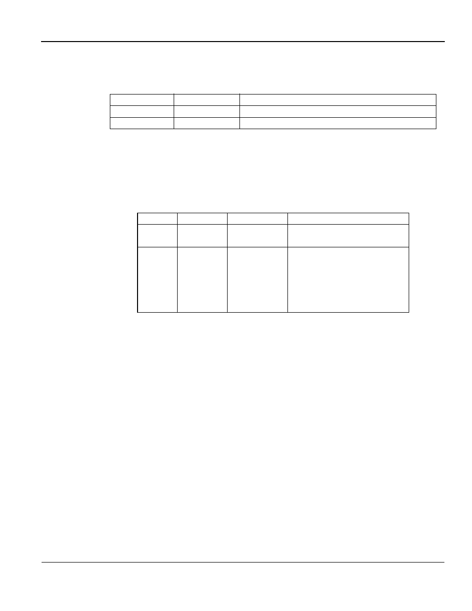
Option card status indications
The following LED’s indicate the option card status.
Profibus-DP Data and I/O Map
The SI-P option card supports an I/O map of 32 bytes input data and 32 bytes of output data.
This data map is fixed and must be used as described. The I/O map is divided into two sections
which are described below.
•Fast I/O data area - Byte 0 - 15.
Parameters in this area are directly transferred to/from the inverter. Information in these
registers is updated every 5ms.
•MODBUS message area - Byte 16 - 31.
This area is used to transfer MODBUS messages to the inverter. All inverter parameters
and data can be accessed within this area. Since the data in this area is processed by the
inverter, it may take several Profibus communication cycles depending on baud rate before
the inverter responds. Therefore, a handshake procedure between master and slave is used
to coordinate data. This handshake is utilized in byte 31 and is described in the MODBUS
Message Area section.
Table 3: Profibus-DP Status - LED Indication
LED
Color
Indication/Function
COMM
Green
On during data exchange with the Profibus-DP master
ERR
Red
On when no data exchange occurs
Table 4: Option Card Status - LED Indication
LED
Color
Light Indication
Function
PWR
Green
ON
OFF
+5V power to the electronics is OK.
+5V is below +4.5V (min)
WD
Two color
Red/Green
OFF
Lit Green
Flashing Green
Lit Red
Flashing Red
Other
Option card CPU not running
Initialization
Normal operation
Internal option card error
G5 error detected
Unspecified, option card error