Modbus response message structure – Yaskawa VS-616G5 Profibus-DP Control Card SI-P User Manual
Page 14
Page 14
VS-616G5 Option Instruction Manual: Profibus-DP Control Card SI-P
MODBUS response message structure
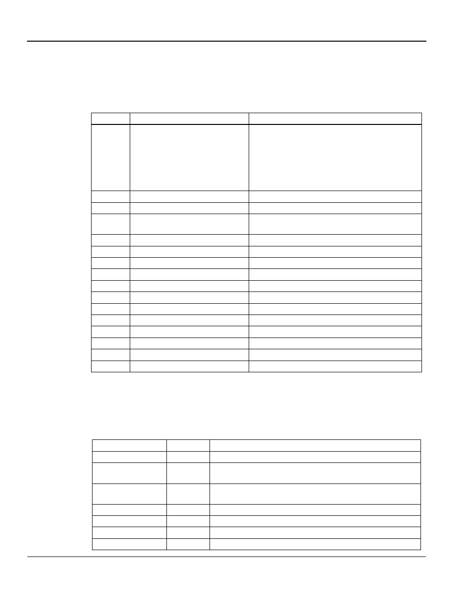
The MODBUS response message is built up in the following way:
If a fault occurs, the option card responds with an ERROR by setting the MSB bit
in the MODBUS Response code to one (1). When this occurs, the MODBUS data
length is set to 02H and the LOW byte for Data word 1 contains the ERROR code.
Table 11: MODBUS Response Message Structure (G5 SI-P
⇒
PDP Master)
Byte
Name
Function
16
MODBUS Function Code
MODBUS Response code.
00H:
Waiting for response from inverter.
03H:
Response for read operation.
10H:
Response for write operation.
83H:
Read command error.
90H: Write
command
error.
Other: Not supported
17
MODBUS Starting address HI
Inverter start address reference, HI byte
18
MODBUS Starting address LOW
Inverter start address reference, LOW byte
19
MODBUS Data Length
Write: No of bytes written to inverter.
Read: No. of valid bytes in the data area
20
MODBUS Data 1
HI byte for Data word 1. Read operation
21
MODBUS Data 1
LOW byte for Data word 1. Read operation
22
MODBUS Data 2
HI byte for Data word 2. Read operation
23
MODBUS Data 2
LOW byte for Data word 2. Read operation
24
MODBUS Data 3
HI byte for Data word 3. Read operation
25
MODBUS Data 3
LOW byte for Data word 3. Read operation
26
MODBUS Data 4
HI byte for Data word 4. Read operation
27
MODBUS Data 4
LOW byte for Data word 4. Read operation
28
Not used
Reserved for future use
29
Not used
Reserved for future use
30
Not used
Reserved for future use
31
Handshake register
See Handshaking Register section
Table 12: Error Code Descriptions
Error
Error Code
Description
Function error
01H
Unregistered MODBUS function code.
Address fault
02H
Parameter address (Starting address) is greater than 600H
Designate unused parameter address.
No. of Data Faults
03H
Read more than 4 words
Write more than 4 words
Data content Fault
21H
Parameter contents exceed the upper or lower limit.
—
22H
Parameters are changed during running or undervoltage condition.
Write Fault
23H
Write parameter during undervoltage
—
24H
Write parameter during calculating parameter.